Summary of Electronic Sudoku Game
This article explains how to build an Arduino-based electronic Sudoku game with a 2.8-inch TFT touch screen, stylus, rechargeable Li-Po battery, and 3D-printed case. It covers required parts, 3D printing settings for the case, wiring the screen to an Arduino Uno, installing three Arduino libraries, and calibrating screen colors and touch coordinates to ensure correct operation.
Parts used in the Electronic Sudoku Game:
- Arduino Uno R3
- 2.8 inch TFT Touch LCD screen
- Li-Po Rechargeable Battery 600mAh 3.7v (max 30mm x 50mm x 6mm)
- TP4056 Lithium Battery Charger Board Micro USB
- Hookup wire
- 3D printed case (Lid and Base)
- 3.3K 1/8 watt resistor
- Small SPDT ON-Off Miniature Slide Toggle Switch
- Touch screen stylus
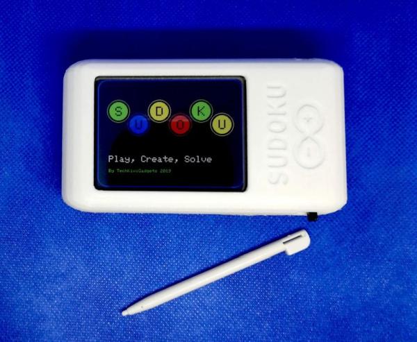
In this post, we will teach you how to create Electronic Sudoku Game: Calling all you Sudoku addicts. Play, Create and Solve Sudoku puzzles using this easy to build Arduino based project.
Simple to use with a touch screen and stylus the unit comes preloaded with Sudoku puzzles to play, a help feature to highlight incorrect values and an automated solver button. This project includes a 3D printed case with only seven components including a USB rechargeable battery so it does not require a high degree of electronics experience to complete.
Steps to create an Electronic Sudoku Game:
Step 1: Gather the Materials
Years ago, just for fun, I wrote an excel macro to solve Sudoku Puzzles on a desktop computer. It occurred to me that this could be incorporated into an Arduino Touch Screen device. The perfect fit for this was an Arduino Uno and a compatible 2.8 inch TFT touch screen shield.
- Arduino Uno R3
- 2.8 inch TFT Touch LCD screen
- Li-Po Rechargeable Battery 600mAh 3.7v (30mm x 50mm x 6mm maximum physical dimensions)
- TP4056 Lithium Battery Charger Board Micro USB
- Hookup wire
- Access to a 3D printer with a minimum 160mm x 70mm x 30mm build capacity
- 3.3K 1/8 watt resistor
- Small SPDT Switch ON-Off Miniature Slide Toggle Switch
Step 2: 3D Print the Case
The 3D case was printed with White PLA with each part oriented so that Lid and Base are facing upwards using the following settings
Layer Height: 0.2mm
Speed: 40mm/s
Nozzle Diameter: 0.4mm
Supports: Enabled
Nozzle Temperature: 210 Degrees
The 3D Model Files are located here on Thingiverse with the touch screen stylus inserts into a cavity under the Arduino PCB and can be removed by sliding out with your finger.
Step 3: Load the Code and Test the Screen
The best place to start is to connect the Arduino Uno with the TFT screen and test the screen. I have subsequently found there are various screens available that have different drivers or settings so here is my recommended approach.
1. Connect the Screen to the Arduino Uno
Carefully align the Arduino Uno and TFT screen pins and ensure they are oriented correctly. In the picture provided, you can see the correct alignment including the noticeable gaps in the Uno and TFT screen pins that help with alignment.
2. Load the Arduino IDE libraries
Firstly download and install the Arduino IDE from here
The code requires the following three libraries to be loaded into the Arduino IDE to enable it to work
- Adafruit_GFX.h – Adafruit GFX graphics core library
- Adafruit_TFTLCD.h – Arduino library for 8-bit TFT LCDs
- TouchScreen.h
3. Calibrate Screen colors and Touch Locations
TFT LCD Screens come with different control chipsets and touchscreen setups. I had quite a challenge with this particular model getting it working and had to make a number of configuration changes before I could get it working satisfactorily.
Fortunately, Adafruit has provided a variety of options to deal with these challenges however you may find some issues you may have to deal with.
Test that the colors and touch locations of the touch screen are consistent with the video and pictures provided.
- If the screen is not working then you may need to change the screen type in the code to ensure correct operation.
- If the touch locations are incorrect then row 218 of the code provides test coordinate data which can be used with Row 39 min/max settings for touch accuracy.
- If the colors are incorrect check they can be changed after row 60 of the code
- If the orientation of the screen is in portrait then row 105 in code can be adjusted
- What main components are required to build the Electronic Sudoku Game?
The article lists an Arduino Uno R3, 2.8 inch TFT touch LCD screen, 600mAh Li-Po battery, TP4056 charger board, hookup wire, 3D printed case, 3.3K resistor, and a small SPDT slide switch. - How is the 3D case printed for the project?
The case is printed in White PLA with Lid and Base facing upwards using 0.2mm layer height, 40mm/s speed, 0.4mm nozzle, supports enabled, and 210°C nozzle temperature. - Which Arduino libraries must be installed to run the Sudoku code?
The code requires Adafruit_GFX.h, Adafruit_TFTLCD.h, and TouchScreen.h libraries. - How should the TFT screen be connected to the Arduino Uno?
Carefully align the Uno and TFT screen pins ensuring correct orientation using the noticeable gaps in the pins for alignment as shown in the article images. - What should I do if touch locations are incorrect?
Use the test coordinate data at row 218 of the code and adjust the min/max settings at row 39 for touch accuracy. - What adjustments fix incorrect screen colors?
Color settings can be changed in the code after row 60 as described in the article. - How do I change the screen orientation if it appears in portrait?
Adjust the orientation setting in the code at row 105. - Where are the 3D model files for the case located?
The 3D model files are available on Thingiverse as stated in the article.