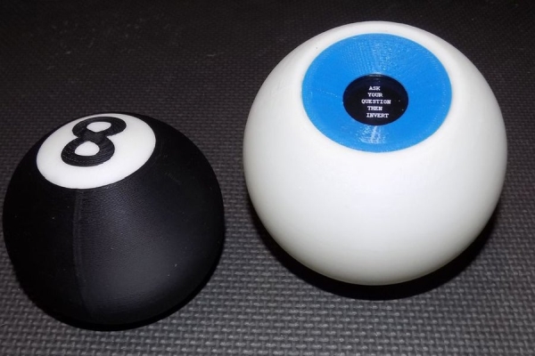
I wanted to create a digital version of the Magic 8 Ball…
The body of this is 3D printed and the display has been changed from an polyhedron in blue dye to a small OLED controlled by a random number generator programmed into an Arduino NANO.
Then I went on a bit of a tangent and created another shell, this one is an ice blue eye that looks straight into your soul…
CAUTION: While I ultimately used mercury tilt switches for my final build. If this intended to be used as a toy, you should just follow the original plan outlined here. Mercury has known toxicity. The second video clearly shows why I did this!
All of my mercury switches were reclaimed from old home thermostats that were destined for the landfill, they are in safe hands now…
UPDATE April 12,2019!!!: I have included a far simpler way to power and run this project. I have also included stripped down code that just displays the advice. All is revealed in step 10.
Step 1: The 8 Ball

I created 100mm hollow sphere in Solidworks
I didn’t want any joining seam along the equator of the sphere so the the top and bottom sections were then cut out leaving a 50mm hole in the top and a 56mm hole in the bottom.
Since I didn’t want any fasteners showing, I then made a 57 mm cut 1mm deep on the outside of the bottom hole and added two 4mm diameter rods that just out perpendicular into the hole about 4mm long.
The top hole plug was modelled by inverting the initial cut out section for the top hole. An additional 2mm ring was added to the inner curve of the plug then the whole thing was made solid.
From the top I drew a large number 8 and this outline was cut out of the top cover. This in turn was used to create a number 8 piece.
Step 2: Window Access Port
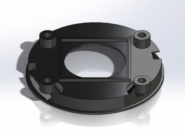
This part holds all of the electronics and inner workings. It is also intended to be the access point to change the batteries.
I wanted no fasteners visible on this so I made the opening a screw in piece it turns about 36 degrees and locks in place..
There is a port that is approximately 1 inch in diameter in the middle of the piece that allows for viewing of the advice.
On the inside of the port is a square cutout area that is meant to house a 2mm thick piece of plastic or glass.
This window is used on all sizes of this toy.
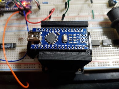
also needed is two of the electronicsBrace part and one each of the ElectronicsTray and nanoTray.
Step 3: Print and Assemble
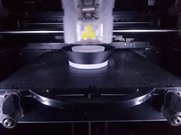
The ball and number were printed using ABS black. While the top cover was printed using ABS natural. I tried ABS white but it looked too stark.
The number 8 is a press fit into the top cap.
The top cap is just small enough to go inside of the ball through the bottom opening.
This is a friction fit but it is also held in place with ABS adhesive.
I was a little concerned about fitting all the parts inside so I went ahead and created another one, this time it was 120mm in diameter.
Step 4: The Eye
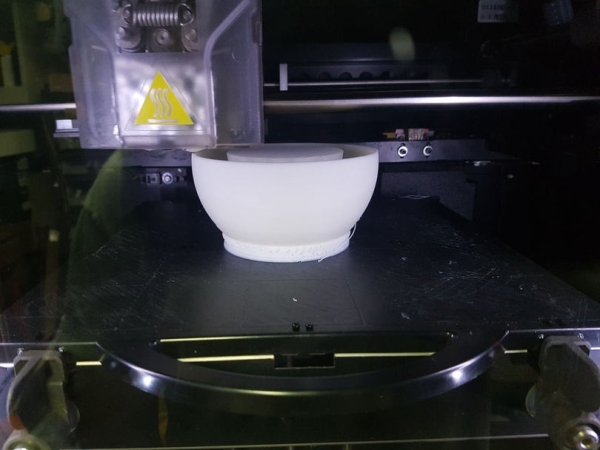
I removed the top cutout in the 3D models and printed both orbs in natural ABS then printed the window access port in Blue ABS.
It gives a reasonable facsimile of an eyeball when looking at it straight on.
I like this version better than the original 8Ball.
Step 5: The Electronics
Space was a constraint as was appearance.
There had to be no outside protrusions or obstructions to the aesthetics.
The toy is powered on and interacted with, by motion.
The toy starts in an off condition until it is inverted.
Instead of a push button switch I used a tilt switch.
Previously I used a MOSFET for controlling power to the microcontroller. This however was not ideal since it allowed a small amount of current to continuously feed the microcontroller, thereby killing the battery in about a month or so.
This case I used a small relay like the one that I used in my cryptex USB drive project.
The included schematic shows the wiring necessary to get the hardware to work.
The relay. I used 6V coil since the battery voltage is 6V and this required a driving circuit for the relay that is switched from a simple NPN transistor.
Waveshare 128 X 128 OLED module from Amazon.
Step 6: The Program
I wanted the answers to be that of the original toy.I used Wikipedia for this.
The module is a SSD1327 type and there is a very robust library of code for these LCDs.
Initial attempts at utilizing this code resulted in failure since the memory usage was too great.
A simple workaround was to make use of the stripped down code supplied by the manufacturer.
I blew out most of the example and used snippets of the original code to display the information that was needed.
The program works as follows:
The ball at rest is in a power off state.
Inverting the ball an looking at the window is the original power on state.
Once the Arduino starts and displays the instructions “Ask Your Question Then Invert”. The program takes over and supplies power to the Arduino through the program controlled relay..
The instructions remain visible until the toy is turned round side up this toggles the tilt switch off and the the program advances into thinking mode. The readout shows “Thinking…” so that you know it is still active.
The ball is then inverted again so that the window is upright.
This action is read by the mechanical tilt switch on and the program will generate a random response in one second of the window being oriented to the top.
The message remains visible until the toy is turned ball side up.
This process continues until the ball is placed window side down for longer than 16 seconds, where the program will deactivate the relay and turn off the power.
CRITICAL NOTES on this program are in the random(); function.
I was having issues with the same responses showing up, I even tested this with both devices at the same time and found that yes they were the same.
It is critical to use the randomSeed(analogRead(0)); routine. The explanation for this can be found HERE:
Step 7: Window and Electronics Assembly
There are five printed parts to this assembly that make up a window, battery holder and cover.
The first is the visible component which has supports for the OLED and the second is the battery and controller carrier which attaches to the window VIA standoffs.
I used a small piece of cut glass for the window. This was glued in place with cyano type adhesive. I had some weatherstrip foam with adhesive on one side, this was cut into small strips and placed around the glass on the inside of the window assembly.
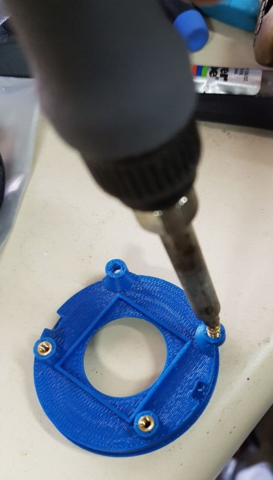
There are 4 screw holes around the window. these are spaced for the module I had chosen. These have 4-40 heat set inserts installed using a soldering iron.
With the module in place, 1/4 inch standoffs are used to fasten it down.
I got lucky when the components arrived, The battery holder just fits inside of the opening which means that I didn’t have to place it vertical. This means that the smaller size ball will work fine.
The base of the electronics bay carries the batteryholder and has 2 cutouts, one for the relay and one for the tilt switch.
The cover has 3 parts that snap together and securely holds the batteries down and provides a flat surface to attach the NANO module to.
These 2 parts are then screwed to the 4 standoffs on the back of the OLD module.
WITH CAUTION! I ended up replacing the tilt switch with a mercury switch. This produced more reliable operation.
Source: Electronic Magic 8 Ball and Eyeball