Summary of Easy Arduino Menus for Rotary Encoders
Rotary encoder with built-in push button is used to navigate and select menu options on an Arduino. The author provides an interrupt-driven sketch that reads encoder rotation and a debounced center button (no delay()), implements a simple if()-based menu with top-level modes and sub-settings, and shows how to store and restore settings. Debug prints use the serial monitor; these can be removed to shrink the sketch. The code is designed to be simple, adaptable, and suitable for fast scrolling and fine control with an encoder.
Parts used in the Easy Arduino Menus for Rotary Encoders:
- Arduino (UNO or compatible)
- Rotary encoder with centre push button
- Wires/jumpers
- Ground connection (from encoder to Arduino GND)
- Digital pins: encoder pins to D2 and D3, button to D4 (or alternate pins as updated in sketch)
- Computer with Arduino IDE and serial monitor
Rotary encoders with built-in buttons are excellent input devices for projects, particularly if you need to navigate menus and make selections. With any luck, this Instructable will empower you to experiment with a simple menu system and pair it with a rotary encoder to elevate the professionalism of your upcoming project!
The reason why menus and rotary encoders require coding.
I wanted to have a menu in an upcoming project and use a rotary encoder with a centre push button as my input hardware. This is really similar to the LCD controllers for RAMPS and Arduino MEGA 3D printers. The rotary encoder will allow me to scroll through the menu options, i.e. navigate the menu, select sub-menus and also change values within sub-menus/settings – very versatile for one hardware interface! A microcontroller is needed to manage all of this and microcontrollers need instructions, AKA code!
Other options
The problem I had with existing Arduino menu libraries and menu code is that for simple menus they were overly complicated. Another drawback of many alternatives was that the code was designed for LCD screens and momentary push buttons, not rotary encoders and adaptable to other display outputs. These menus were geared around selecting between a small number of modes and incrementing values relatively slowly. We know that rotary encoders are a great hardware input option because they afford relatively fast input value changes while retaining fine control at slow speed. I wanted to write code which would allow unambiguous top level menu navigation but also allow you to quickly scroll through a large range of values within each sub-menu/setting, exploiting the strengths of the rotary encoder.
The approach
I decided to follow some advice to use if() statements for a simple menu structure and keep it sketch-based. The resultant code builds on my previous Instructable which sought to reliably read the rotation pulses and direction. Please check it out for background.
In this sketch, we add the reading of the centre push button on the rotary encoder shaft, using code that Nick Gammon developed to record button state changes with debouncing and without relying on the Arduino’s delay() function
that hinders the microcontroller from running different code and could cause significant delays in our sketch, such as sluggish display updates. Using code to change the state of a button is more beneficial than simply detecting whether the button is in a high or low digital logic when making a single selection, such as choosing a menu option, as it can avoid accidental multiple selections with each press of the button.
Let’s examine the requirements for setting up the example code in Step 1.
Step 1: Preparation
If you haven’t yet, please see my other Instructable on rotary encoder reading to find out how to set up your hardware and Arduino IDE software.
If you haven’t yet, please see my other Instructable on rotary encoder reading to find out how to set up your hardware and Arduino IDE software.
Hardware
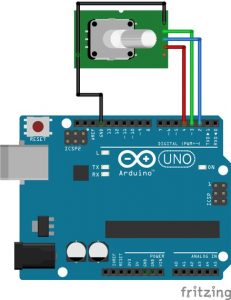
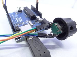
The images depict the extra hardware connections required to utilize the center push button. I utilized Fritzing for the diagram, but it lacked a rotary encoder component showing the pin layout. So, refer to the diagram, notes, and rotary encoder photo for a better understanding of the pin layout.
One of the two pins on the side of the rotary encoder (not the three-pin side) should be linked to ground, while the other should be connected to a digital pin on the Arduino. I have utilized D4 for the demonstration sketch. If you decide to use a different pin, make sure to update the value of buttonPin in the sketch.
Step 2 is up next with the code.
Step 2: Code
This is the code. By looking at the structure and the comments I hope you will find it easy to adapt for your specific needs!
/*******Interrupt-based Rotary Encoder Menu Sketch*******
 * by Simon Merrett, based on insight from Oleg Mazurov, Nick Gammon, rt and Steve Spence, and code from Nick Gammon
 * 3,638 bytes with debugging on UNO, 1,604 bytes without debugging
 */
// Rotary encoder declarations
static int pinA = 2; // Our first hardware interrupt pin is digital pin 2
static int pinB = 3; // Our second hardware interrupt pin is digital pin 3
volatile byte aFlag = 0; // let's us know when we're expecting a rising edge on pinA to signal that the encoder has arrived at a detent
volatile byte bFlag = 0; // let's us know when we're expecting a rising edge on pinB to signal that the encoder has arrived at a detent (opposite direction to when aFlag is set)
volatile byte encoderPos = 0; //this variable stores our current value of encoder position. Change to int or uin16_t instead of byte if you want to record a larger range than 0-255
volatile byte oldEncPos = 0; //stores the last encoder position value so we can compare to the current reading and see if it has changed (so we know when to print to the serial monitor)
volatile byte reading = 0; //somewhere to store the direct values we read from our interrupt pins before checking to see if we have moved a whole detent
// Button reading, including debounce without delay function declarations
const byte buttonPin = 4; // this is the Arduino pin we are connecting the push button to
byte oldButtonState = HIGH;  // assume switch open because of pull-up resistor
const unsigned long debounceTime = 10;  // milliseconds
unsigned long buttonPressTime;  // when the switch last changed state
boolean buttonPressed = 0; // a flag variable
// Menu and submenu/setting declarations
byte Mode = 0;   // This is which menu mode we are in at any given time (top level or one of the submenus)
const byte modeMax = 3; // This is the number of submenus/settings you want
byte setting1 = 0;  // a variable which holds the value we set
byte setting2 = 0;  // a variable which holds the value we set
byte setting3 = 0;  // a variable which holds the value we set
/* Note: you may wish to change settingN etc to int, float or boolean to suit your application.
 Remember to change "void setAdmin(byte name,*BYTE* setting)" to match and probably add some
 "modeMax"-type overflow code in the "if(Mode == N && buttonPressed)" section*/

void setup() {
  //Rotary encoder section of setup
  pinMode(pinA, INPUT_PULLUP); // set pinA as an input, pulled HIGH to the logic voltage (5V or 3.3V for most cases)
  pinMode(pinB, INPUT_PULLUP); // set pinB as an input, pulled HIGH to the logic voltage (5V or 3.3V for most cases)
  attachInterrupt(0,PinA,RISING); // set an interrupt on PinA, looking for a rising edge signal and executing the "PinA" Interrupt Service Routine (below)
  attachInterrupt(1,PinB,RISING); // set an interrupt on PinB, looking for a rising edge signal and executing the "PinB" Interrupt Service Routine (below)
  // button section of setup
  pinMode (buttonPin, INPUT_PULLUP); // setup the button pin
  // DEBUGGING section of setup
  Serial.begin(9600);     // DEBUGGING: opens serial port, sets data rate to 9600 bps
}

void loop() {
  rotaryMenu();
  // carry out other loop code here
}

void rotaryMenu() { //This handles the bulk of the menu functions without needing to install/include/compile a menu library
  //DEBUGGING: Rotary encoder update display if turned
  if(oldEncPos != encoderPos) { // DEBUGGING
    Serial.println(encoderPos);// DEBUGGING. Sometimes the serial monitor may show a value just outside modeMax due to this function. The menu shouldn't be affected.
    oldEncPos = encoderPos;// DEBUGGING
  }// DEBUGGING
  // Button reading with non-delay() debounce - thank you Nick Gammon!
  byte buttonState = digitalRead (buttonPin);
  if (buttonState != oldButtonState){
    if (millis () - buttonPressTime >= debounceTime){ // debounce
      buttonPressTime = millis ();  // when we closed the switch
      oldButtonState =  buttonState;  // remember for next time
      if (buttonState == LOW){
        Serial.println ("Button closed"); // DEBUGGING: print that button has been closed
        buttonPressed = 1;
      }
      else {
        Serial.println ("Button opened"); // DEBUGGING: print that button has been opened
        buttonPressed = 0;
      }
    }  // end if debounce time up
  } // end of state change

  //Main menu section
  if (Mode == 0) {
    if (encoderPos > (modeMax+10)) encoderPos = modeMax; // check we haven't gone out of bounds below 0 and correct if we have
    else if (encoderPos > modeMax) encoderPos = 0; // check we haven't gone out of bounds above modeMax and correct if we have
    if (buttonPressed){
      Mode = encoderPos; // set the Mode to the current value of input if button has been pressed
      Serial.print("Mode selected: "); //DEBUGGING: print which mode has been selected
      Serial.println(Mode); //DEBUGGING: print which mode has been selected
      buttonPressed = 0; // reset the button status so one press results in one action
      if (Mode == 1) {
        Serial.println("Mode 1"); //DEBUGGING: print which mode has been selected
        encoderPos = setting1; // start adjusting Vout from last set point
      }
      if (Mode == 2) {
        Serial.println("Mode 2"); //DEBUGGING: print which mode has been selected
        encoderPos = setting2; // start adjusting Imax from last set point
      }
      if (Mode == 3) {
        Serial.println("Mode 3"); //DEBUGGING: print which mode has been selected
        encoderPos = setting3; // start adjusting Vmin from last set point
      }
    }
  }
  if (Mode == 1 && buttonPressed) {
    setting1 = encoderPos; // record whatever value your encoder has been turned to, to setting 3
    setAdmin(1,setting1);
    //code to do other things with setting1 here, perhaps update display
  }
  if (Mode == 2 && buttonPressed) {
    setting2 = encoderPos; // record whatever value your encoder has been turned to, to setting 2
    setAdmin(2,setting2);
    //code to do other things with setting2 here, perhaps update display
  }
  if (Mode == 3 && buttonPressed){
    setting3 = encoderPos; // record whatever value your encoder has been turned to, to setting 3
    setAdmin(3,setting3);
    //code to do other things with setting3 here, perhaps update display
  }
}

// Carry out common activities each time a setting is changed
void setAdmin(byte name, byte setting){
  Serial.print("Setting "); //DEBUGGING
  Serial.print(name); //DEBUGGING
  Serial.print(" = "); //DEBUGGING
  Serial.println(setting);//DEBUGGING
  encoderPos = 0; // reorientate the menu index - optional as we have overflow check code elsewhere
  buttonPressed = 0; // reset the button status so one press results in one action
  Mode = 0; // go back to top level of menu, now that we've set values
  Serial.println("Main Menu"); //DEBUGGING
}

//Rotary encoder interrupt service routine for one encoder pin
void PinA(){
  cli(); //stop interrupts happening before we read pin values
  reading = PIND & 0xC; // read all eight pin values then strip away all but pinA and pinB's values
  if(reading == B00001100 && aFlag) { //check that we have both pins at detent (HIGH) and that we are expecting detent on this pin's rising edge
    encoderPos --; //decrement the encoder's position count
    bFlag = 0; //reset flags for the next turn
    aFlag = 0; //reset flags for the next turn
  }
  else if (reading == B00000100) bFlag = 1; //signal that we're expecting pinB to signal the transition to detent from free rotation
  sei(); //restart interrupts
}

//Rotary encoder interrupt service routine for the other encoder pin
void PinB(){
  cli(); //stop interrupts happening before we read pin values
  reading = PIND & 0xC; //read all eight pin values then strip away all but pinA and pinB's values
  if (reading == B00001100 && bFlag) { //check that we have both pins at detent (HIGH) and that we are expecting detent on this pin's rising edge
    encoderPos ++; //increment the encoder's position count
    bFlag = 0; //reset flags for the next turn
    aFlag = 0; //reset flags for the next turn
  }
  else if (reading == B00001000) aFlag = 1; //signal that we're expecting pinA to signal the transition to detent from free rotation
  sei(); //restart interrupts
}
// end of sketch!
I have inserted “DEBUGGING” at the beginning of each comment on non-essential lines for the menu to function. If you are satisfied with how the menu operates, you may consider annotating or removing these lines to reduce the size of the compiled sketch.
It is important to provide users with feedback as they navigate through menu options and settings. If you opt out of adding the DEBUGGING lines, consider using a different visual cue (such as an LCD text display or LEDs) to show that the encoder inputs are moving through the menu and adjusting settings.
If I remove the DEBUGGING lines (while remembering that some visual feedback for menu navigation is still necessary), the final code size for Arduino Uno is approximately 1,650 bytes, which should allow room for the more interesting sections of your sketch on the ATMEGA328P!
Proceed to Step 3 to understand the functionality of the menu system.
Step 3: Operation and Conclusion
Operation
When you open the serial monitor in Arduino after uploading this sketch, and begin rotating the encoder shaft, you will notice the main menu rotating through the available sub-menus/options (restricted by the modeMax variable). Pressing the center-push button selects the mode/sub-menu you are on, allowing you to freely scroll through values ranging from 0 to 255 in that sub-menu. If you press the center-push button, the value will be set to setting1, setting2, setting3, etc. The Arduino immediately takes you back to the main menu after this action.
While on, the Arduino stores the settings you choose and if you revisit a sub-menu for a setting you’ve already adjusted, it will begin the encoder adjustments from the last value selected!
Conclusion
I started to create code based on sketches that would enable rotary encoders to navigate a simple menu for Arduinos. I also attempted to ensure readability, allowing users to easily understand the menu structure and necessary code adjustments for customization, unlike other options.
This code is simple and universal, designed to illustrate the functionality and can be easily customized for your own use. It utilizes the serial monitor as a simple debugging tool, eliminating the requirement for an additional display to observe the code’s functionality. I hope it is helpful and encourages you to edit, modify, and enhance it!
Please leave a comment sharing any activities or information you use it for!
- How does the sketch read the rotary encoder?
The sketch uses hardware interrupts on digital pins 2 and 3 with interrupt service routines PinA and PinB to detect detents and update encoderPos. - How is the centre push button debounced without delay?
Button state changes are timed using millis and a debounceTime of 10 ms following Nick Gammon's approach; buttonPressTime and oldButtonState track changes. - Can the encoder button pin be changed from D4?
Yes; the sketch uses buttonPin set to 4 but instructs you to update buttonPin in the code if you use a different Arduino pin. - What happens when I press the button while on the main menu?
The current encoderPos is stored into Mode, the corresponding Mode is selected, and encoderPos is set to the stored setting for that Mode to begin adjustments. - How are settings saved and restored when revisiting a submenu?
Each setting (setting1, setting2, setting3) stores the last encoderPos; when entering that Mode the sketch assigns encoderPos = settingN so adjustments start from the last value. - How does the code prevent encoderPos from going out of bounds on the main menu?
The code checks encoderPos against modeMax and wraps or corrects it: if greater than modeMax it sets encoderPos to 0, and if much larger it sets it to modeMax. - Does the sketch require an LCD display to work?
No; the example uses the serial monitor for debugging and feedback, though it suggests adding visual feedback like an LCD or LEDs if DEBUGGING prints are removed. - What does the setAdmin function do after saving a setting?
setAdmin prints the setting (debugging), resets encoderPos to 0, clears buttonPressed, sets Mode back to 0, and prints Main Menu.