Summary of DMX Effect Controller
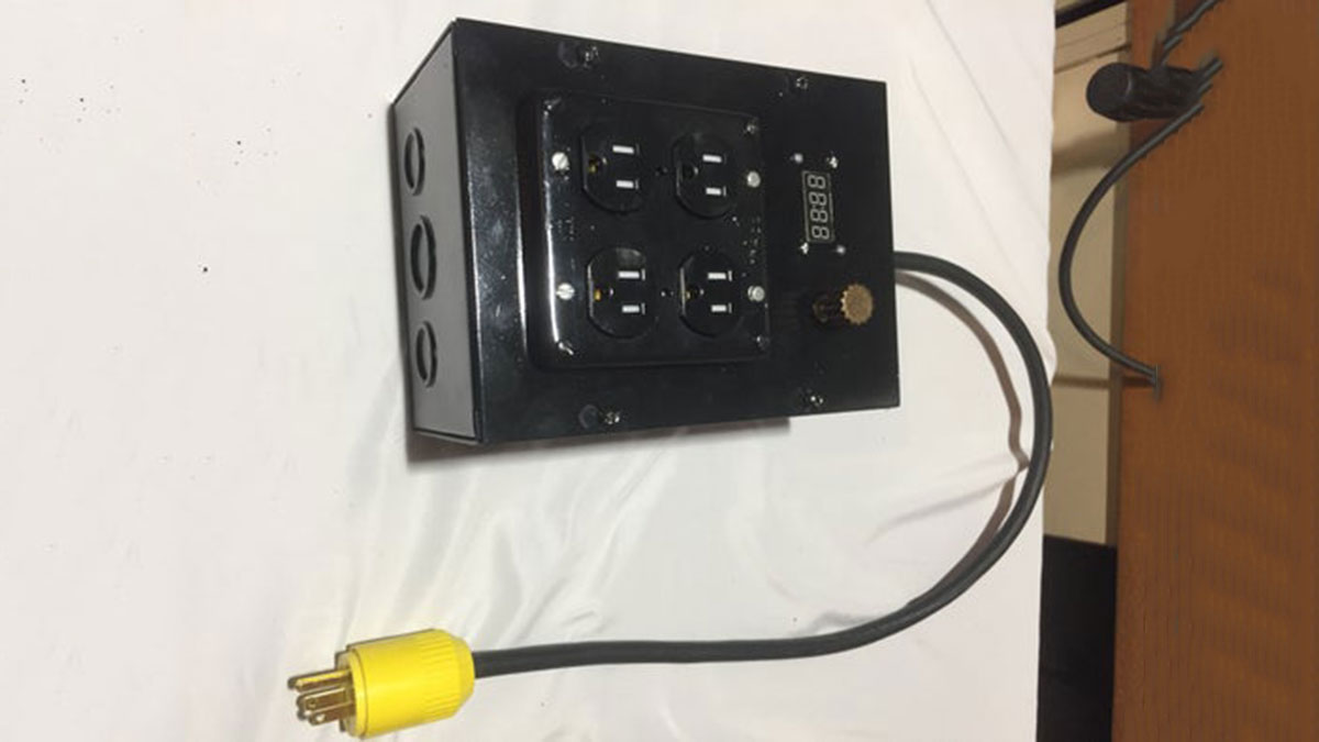
This project details the construction of a DMX-controlled plug box that enables remote triggering of stage effects and props via a lighting console. By integrating an Arduino UNO, MAX485 module, and relay system, the device allows users to select and save one of four DMX addresses using a rotary encoder and LCD display. The controller provides 120V AC power to two receptacles on cue, eliminating the need for separate backstage operators or control systems while supporting daisy-chained DMX peripherals.
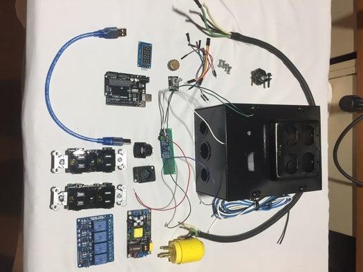
Parts used in the DMX Effect Controller:
- Enclosure box with knockouts and cutouts
- 2 dual 120V/15A receptacles
- AC power cord
- 16ga. wire
- Jumper wires
- Mounting screws and posts
- Arduino UNO and USB cable
- Rotary encoder with button capability
- Nifty 3D printed knob
- 4 digit, 7 segment LCD display
- MAX485 RS-485 module
- Panel mount DMX connectors (male and female)
- 12v Power supply
- 5V 4 relay module
The goal of this project was to make a DMX-Controlled plug box which would allow on-stage effects or devices to be triggered remotely from the lighting console. This could potentially eliminate the need for a separate control system and operator backstage. This controller could be used in a wide variety of applications including:
-Triggering FX (solenoid, motor, other micro-controller, etc.)
-Triggering practical props (lamps, radios, buzzers, etc.)
-Backstage cue light systems
The controller includes standard 5-pin DMX input and thru connectors mounted to the exterior of the box, which allows it to easily be daisy chained with other DMX peripherals. There is an onboard channel selector knob and display which allow the user to select and save the first of the four controllable DMX addresses/channels
The receptacles in this controller are not dimmable; they are meant only to provide 120V AC power on cue. Each receptacle has a maximum load of 10A due to the limits of the relays and wiring.
Step 1: What You’ll Need
Physical Components:
- Enclosure box for:
- 2 dual 120V/15A receptacles
- All Electronic components
- Knockouts for AC power, DMX Input, DMX Thru
- Cutouts for LCD display, Rotary encoder knob
- AC power cord
- 16ga. wire for wiring relays to receptacles
- Jumper wires for electronics
- Assorted mounting screws and posts
- Arduino UNO and USB cable
- Rotary encoder w/button capability
- Nifty 3D printed knob (or buy one or don’t)
- 4 digit, 7 segment LCD display
- MAX485 RS-485 module
- Panel mount DMX (male and female)
- Power supply (I used 12v)
- 5V 4 relay module
Arduino Libraries Used:
- EEPROM.h (to save DMX address in onboard memory)
- Arduino.h
- TM1637Display.h (LCD Display)
- Conceptinetics.h (DMX Slave)
Step 2: Suggestion: Breadboard Prototyping
I would highly recommend breadboarding, assembling all of the electronic components, uploading the sketch, connecting to a DMX controller (like a lighting control console) and testing things out before adding the AC power components and the enclosure. This way, you’ll know you’re on the right track before you have everything crammed in the box and it becomes nearly impossible to make quick alterations.
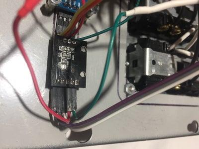
Step 3: MAX485 DMX Slave Setup
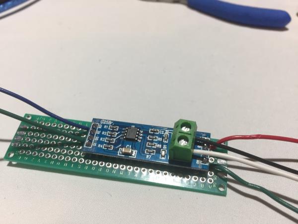
I used a MAX485 module set up as a “slave” to receive the DMX packets. The connections are as follows:
- GND to 5-pin DMX pin1, to DE &RE, and to GND on Arduino
- A to 5-pin DMX pin3
- B to 5-pin DMX pin2
- VCC to +5V
- RO to Pin0 on Arduino
- DI not usedpin
-Later in the process you will use jumpers to connect pins 1-3 of the DMX input jack to pins 1-3 of the DMX thru jack.
-I later used the far end of this PCB to consolidate all ground and +5v connections before jumping one wire to the Arduino
*IMPORTANT* – You must unplug the jumper to Pin0 any time you upload a sketch, as this pin is also used in serial com. when uploading.
Step 4: 4 Digit 7 Segment LCD Display
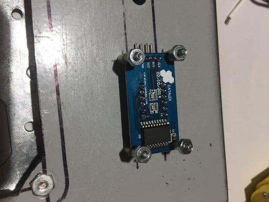
This display is used to read out the DMX start address (out of 4) that has been selected with the encoder.
I cut a hole in the enclosure and created custom mounts for this piece of hardware. Connections are as follows:
GND -> GND
VCC -> +5V
DIO -> Pin5 (orange wire)
CLK -> Pin6 (yellow wire
Step 5: Encoder Knob and Button
I used a 20 position rotary encoder w/push button functionality so that the knob could be used to set the DMX start address and, with a button push, save it to EEPROM so that the unit can be unplugged from power without forgetting a saved address. The address CAN be actively changed with the rotary encoder even after the address is saved, but the saved address will re-load on reset. With a slight tweak in the code, you can make it so the saved address cannot be overwritten by turning the knob without a re-set.
Here are the connections:
GND -> Arduino GND
VCC -> +5V
CLK -> Pin2 (purple)
DT -> Pin3 (gray)
SW (button) -> Pin4 (white)
The encoder is mounted next to the display and was mounted by drilling a hole and using then included nut and washer.
I decided to 3D print a custom knob for my controller box using Fusion 360 and a MakerBot Replicator.
Source: DMX Effect Controller
- What is the primary goal of this project?
The goal is to create a DMX-Controlled plug box that allows on-stage effects or devices to be triggered remotely from a lighting console. - Can the receptacles in this controller be dimmed?
No, the receptacles are not dimmable; they are meant only to provide 120V AC power on cue. - What is the maximum load per receptacle?
Each receptacle has a maximum load of 10A due to the limits of the relays and wiring. - How many controllable DMX addresses can be saved?
The user can select and save the first of four controllable DMX addresses/channels. - Which library is used to save the DMX address in onboard memory?
The EEPROM.h library is used to save the DMX address in onboard memory. - Why is breadboarding recommended before final assembly?
Breadboarding allows you to test electronic components and code before adding AC power and cramming everything into the enclosure. - What happens if the unit loses power after saving an address?
The saved address will re-load on reset because it is stored in the EEPROM. - Which pin on the Arduino connects to the RO pin of the MAX485 module?
The RO pin connects to Pin0 on the Arduino.