Summary of Show Winch
This article details the construction of a wireless theatre winch designed for lifting small objects like chandeliers in spaces lacking a fly system. The project utilizes two wheelchair motors, Arduino microcontrollers, and nRF24L01 transceivers for remote control via programmable cues. Fabrication involves 3D printed cable drums mounted on steel chassis with welded box tube frames. The system features a deadman switch mechanism where releasing the button stops the motor, while emergency power cuts engage electromagnetic brakes.
Parts used in the Theatre Winch:
- Jazzy brand wheelchair motors (2)
- Arduino Uno boards (2)
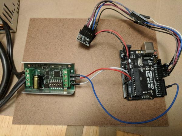
- nRF24L01 transceivers with backpacks (2)
- SyRen10 motor driver
- 24 volt power supply
- 5 volt power supply
- 10k ohm resistors
- Momentary Push buttons
- 3d Printed Material
- Fabrication Material including steel for chassis, screws, and bolts
- 1/16 inch aircraft cable
For this project, I wanted to create a winch that would be functional for use in a show in a theatre. Often, we have to fly in and out small objects, like chandeliers. This unit would be ideal for raising and lowering small objects in spaces that did not have a fly system, or for circumstances where a full batten would be overkill for the application.
Step 1: Parts
To duplicate this, you’ll need to gather some parts. I began by sourcing a motor for this project, and was able to snag two Jazzy brand wheelchair motors on eBay. Other parts I used for this project were:
()2 Arduino Uno boards
(2) nRF24L01 transceivers, with backpacks
(1) SyRen10 motor driver
(1) 24 volt power supply
(1) 5 volt power supply
10k ohm resistors
Momentary Push buttons
3d Printed Material
Fabrication Material- steel for a chassis, screws, bolts, etc.
Step 2: Fabrication
The first step I did was to test the motor and ensure that it would function. I tested the wiring, and figured out which wires were connected to the electromagnetic brakes and which were connected to the motor. By running 24 volts to the brakes, they would release and allow the motor to turn freely.
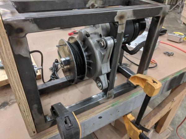
I began 3d printing parts for the 3″ cable drum, which sits on the shaft of the motor. I cut two 5″ disks from steel and after drilling a hole in them, mounted them on either side of the 3d printed drum. I welded up a chassis to bolt the motor to from some 1″ box tube steel. After assembling the cable drum and mounting the winch to the chassis, I was ready to move on from hardware.
Step 3: Software
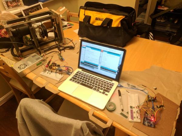
The coding went through many test iterations to figure out the best method of wireless control. One version had a knob controlling speed and direction with a GO button. This was very convenient for adjusting something on the fly, but was not repeatable.
The final version of the code is designed with programmable cues that execute upon command. For this version, there are only two cues available to select from, which are programmed in the Arduino software. Those of you with more than 3 pushbuttons remaining in their kit could easily expand the capabilities. Selecting the cue loads the information into the current cue, and then pressing and holding the GO button commands the motor to move. Releasing the button automatically stops the motor, functioning as a kind of deadman switch. Finally, as a kind of emergency stop, cutting power to the motor by flipping the switch on the power strip, or unplugging it from the wall, will engage the brakes and stop the motor.
My code for the transmitter is embedded below.
<p>/* Transmitter Code<br>*  Code to store a cue and transmit it with a RF24L01+ to a receiver
*  Credit to Mark Hughes for sharing his remote control project that
*  helped me understand and debug my nRF24L01 setup
*
*  This is the code for the transmitter portion for my winch project.
*  It consists of 2 buttons, each with cue information, and a third button
*  which is the "GO" button.  Pressing and holding the button transmits to
*  the receiver the information for the motor controller.
*
*   Hook Up from nRF24L01
*   Gnd to GND
*   VCC to VCC
*   CE to Digital 9
*   CSN to Digital 10
*   SCK to Digital 13
*   MOSI to Digital 11
*   MISO to Digital 12
*   IRQ to Digital 8
*/</p><p>#include SPI.h<spi.h>
#include RF24.h<rf24.h></rf24.h></spi.h></p><p>// Radio Configuration</p><p>RF24 radio(9,10);
byte addresses[][6] = {"1Node","2Node"};
bool radioNumber=1;
bool role = 1;  //Control transmit 1/receive 0</p><p>//hardware attachments
const int GoButton = 4;  //hold button to run loaded cue
const int Cue1 = 3;  //press button to load cue
const int Cue2 = 2;   //press button to load cue
const int ledPin = LED_BUILTIN;  //LED flashes for debug purposes</p><p>//variables
int GoButtonState = 0;
int Cue1State = 0;
int Cue2State = 0;
int MotorSpeed = 0;
int STOP = 0;  //for deadman switch.  Constant broadcast a 0 speed to winch for safety</p><p>void setup() {
  // put your setup code here, to run once:
  pinMode (ledPin, OUTPUT);
  pinMode (GoButton, INPUT);
  pinMode (Cue1, INPUT);
  pinMode (Cue2, INPUT);</p><p>  Serial.begin(9600);                   // Get ready to send data back for debugging purposes
    radio.begin();                        // Get the transmitter ready
    radio.setPALevel(RF24_PA_LOW);        // Set the power to low
    radio.openWritingPipe(addresses[1]);  // Where we send data out
    radio.openReadingPipe(1,addresses[0]);// Where we receive data back</p><p>}</p><p>void loop() {
  // put your main code here, to run repeatedly:
 GoButtonState = digitalRead(GoButton);
 Cue1State = digitalRead(Cue1);
 Cue2State = digitalRead(Cue2);</p><p> //  Serial.print(ForeAft_Output);
    radio.stopListening();                                 // Stop listening and begin transmitting
    delay(50);                                            // make delay longer for debugging
    </p><p>  while (digitalRead(GoButton) == HIGH) {
    SendMotorSignal(); //subroutine for broadcast
  }</p><p>  if (Cue1State == HIGH) {
    MotorSpeed = -127;  //speed for Cue1.  Input can be from -127 to 127
    digitalWrite(ledPin,HIGH);  //LED flashing is helpful for debug
    delay(100);
    digitalWrite(ledPin, LOW);
    delay(200);
  }</p><p>  if (Cue2State == HIGH) {
    MotorSpeed = 127;  //speed for Cue2.  Input can be from -127 to 127
    digitalWrite(ledPin, HIGH);  //LED flashing is helpful for debug
    delay(200);
    digitalWrite(ledPin, LOW);
    delay(100);
  }
  else {
    digitalWrite(ledPin, LOW);
    radio.stopListening();                                 // Stop listening and begin transmitting
    delay(50);                                            // make delay longer for debugging
    if(radio.write(&STOP, sizeof(STOP)),Serial.println("sent STOP"));  //Deadman switch function. Sends value of 0
    radio.startListening();
    //delay(50);  //make delay longer for debugging

  }
}
//subroutine for sending signal to motor
void SendMotorSignal() {
  radio.stopListening();
    delay(50);  //make delay longer for debugging
    if(radio.write(&MotorSpeed, sizeof(MotorSpeed)), Serial.println("sent MotorSpeed"),(MotorSpeed));

    digitalWrite(ledPin,HIGH);  //LED helpful for debug
    delay(100);
    digitalWrite(ledPin, LOW);
    delay(50);
}</p>
And for the receiver.
<p>/*  Receiver Code <br>*   Code to receive data from RF24L01+ and use it to control a motor
*   Thanks to Mark Hughes for sharing his remote control project that was
*   incredibly valuable to me for learning how to make the radio library function.
*
*   This is the code for the receiver portion for my winch project.  It listens
*   for the motor speed information to be transmitted, then sends it to the SyRen
*   motor controller using a simplified serial packet.
*
*   The receiver is using Software Serial to have the communication line to the SyRen
*   on Pin 3, primarily so that the Arduino can be plugged into the computer
*   during development.
*
*   Hook Up from nRF24L01
*   Gnd to GND
*   VCC to VCC
*   CE to Digital 9
*   CSN to Digital 10
*   SCK to Digital 13
*   MOSI to Digital 11
*   MISO to Digital 12
*   IRQ to Digital 8
*   */</p><p>#include <softwareserial.h>  SoftwareSerial.h     //for serial communication on a designated pin
#include <syrensimplified.h>  SyRenSimplified.h  //library for SyRen
#include   SPI.h<spi.h>
#include RF24.h<rf24.h></rf24.h></spi.h></syrensimplified.h></softwareserial.h></p><p>//SyRen Config
SoftwareSerial SWSerial(NOT_A_PIN, 3); // RX on no pin (unused), TX on pin 3 (to S1).
SyRenSimplified SR(SWSerial); // Use SWSerial as the serial port.</p><p>//Radio Configuration</p><p>bool radioNumber=0;
RF24 radio(9,10);
byte addresses[][6] = {"1Node","2Node"};
bool role = 0;  //Control transmit/receive</p><p>// Create variables to control servo value</p><p>unsigned int MotorSpeed;       // Expected range -127 to 127</p><p>void setup() {


    Serial.begin(9600);        // Get ready to send data back for debugging purposes
    SWSerial.begin(9600);      // for communication to SyRen

    radio.begin();             // Initialize radio
    radio.setPALevel(RF24_PA_LOW);    // Set the power output to low
    radio.openWritingPipe(addresses[0]);
    radio.openReadingPipe(1,addresses[1]);
    radio.startListening();
}
void loop() {
    delay(50);               //increase for debuggy, decrease to decrease jitter
    if(radio.available()){
        radio.read(&MotorSpeed,sizeof(MotorSpeed));
        }
        else {Serial.print("No radio");


    }
    //Serial.print(MotorSpeed);  //for debug purposes
    //Serial.print("\t");
    //delay(100);
    //delay can be helpful when debugging- can be finetuned, but no delay causes
    //glitches to happen in serial monitor.  I think there may be conflict
    //between SWSerial to the Syren and nRF and USB serial.

    SR.motor(MotorSpeed);   // Command the motor to move or, where the magic happens

    }</p>
And that’s it for coding!
Step 4: Full Scale Testing
Here are some videos where I’m testing the winch in the shop under load, along with some additional pictures of the components.
A few thoughts-
The chassis is designed to be mountable in different orientations, and accommodates easily the addition of c-clamps, cheeseboroughs, or being mounted directly to the floor or deck. With wireless setup, the winch only needs 120 volt power to function along with its receiver. The transmitter is only a separate power supply, and so also needs an outlet to plug into.
Speed-
I’m getting about 2 feet of travel per second in both the up and down directions running at maximum speed, which is a pretty good pace, and matches the speed of the JR Clancy Powerlift system.
Capacity-
The winch will hold 10 pounds. It will probably hold more than that, but 10 pounds is the most that I have put on it….so far. Without doing destructive testing on the system, it’s difficult to guess what the point of failure would be. The cable is 1/16″ inch aircraft cable, and has a breaking strength of 480 pounds. I don’t know if that would fail first, or if the shaft on the motor would break, or the 3d printed drum would crush or tear.
However, for objects in the 10-20 pound range, I think this winch will function perfectly.
Expansion-
There’s a few elements that I am still working on. There is an encoder and kangaroo board waiting to be be troubleshot and reinstalled on the system, but I had difficulties getting the encoder and Kangaroo to accept each other to run the mandatory tuning cycle. Once that is in place, the winch will have programmable position capabilities. The other item that this needs is a limit switch at the top of travel, to prevent the payload from crashing into the winch.
Source: Show Winch
- How does the winch stop when the user releases the button?
Releasing the GO button functions as a deadman switch that automatically sends a zero speed signal to stop the motor. - What is the maximum capacity the winch can currently hold safely?
The author has tested the winch holding 10 pounds and believes it will function perfectly for objects in the 10-20 pound range. - Does the winch have an emergency stop feature?
Yes, cutting power to the motor by flipping a switch or unplugging it engages the electromagnetic brakes to stop the motor immediately. - How fast does the winch travel at maximum speed?
The winch achieves about 2 feet of travel per second in both up and down directions at maximum speed. - Can the winch be mounted in different ways?
The chassis is designed to be mountable in different orientations and accommodates c-clamps, cheeseboroughs, or direct mounting to the floor. - What type of cable is used for the drum?
The project uses 1/16 inch aircraft cable which has a breaking strength of 480 pounds. - How many programmable cues are available in the current software version?
The final code version allows for two programmable cues that can be selected before execution. - What components are needed to expand the winch capabilities later?
Future expansion requires an encoder, a Kangaroo board, and a limit switch at the top of travel to prevent payload crashes.