This project idea came to me when I was sitting on a bed on a hotel room on vacation. I thought: “It’d be really neat to have a robotic hand that I can control with my own hand!” Upon returning home, I embarked upon a journey to design and create the project. I hope you enjoy!
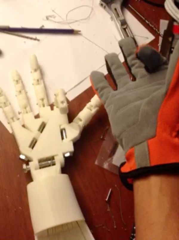
The basic components of the hand and glove are the hand itself, the servos, the Arduino, the glove, and the flex sensors. The glove is mounted with flex sensors: variable resistors that change their value when bent. They’re attached to one side of a voltage divider with resistors of a constant value on the other side. The Arduino reads the voltage change when the sensors are bent, and triggers the servos to move a proportional amount. The servos pull strings that act as tendons, allowing the fingers to move. Here’s a video of it in action (http://m.youtube.com/watch?v=qMtHEOxHDGo):
This guide will show you all the steps required to build your own robotic hand and control glove!
Step 1: Gather the Materials
In total, this project will cost about $100-150, depending on where you get some of the parts. Here’s the parts list:
5x MG946R Servos (or equivalent – MG995 or MG996 should work too. I’ve had a bit of trouble with the range of motion, so servos that support more degrees of rotation would be better) – I got mine from hobbyking.com, but for a less expensive option I’d go with eBay (they come directly from China, so shipping may take longer).
5x 4.5 inch flex sensors – I got mine here:http://microcontrollershop.com/product_info.php?products_id=3802
1x Arduino Uno or equivalent (they’re also much cheaper on eBay)
5x 22k resistors
1x 6.0-7.2V battery (for the servos) – I used this: http://www.all-battery.com/Tenergy7.2V3000mAhRCCarNiMHBatteryPackwithCharger-91103.aspx
1x small breadboard
1x battery connector – something like this: http://www.radioshack.com/product/index.jsp?productId=2103292
Breadboard jumpers/hookup wire
1x small blank PCB – I used something like this, only square: http://www.radioshack.com/product/index.jsp?productId=12516741
1x right hand glove (should be sturdy and fit well)
1x 8mm diameter 55mm long bolt
1x 8mm diameter 60mm long bolt
1x 8mm diameter 80mm long bolt
14x 3mm diameter about 20mm long screws
20x 4mm diameter screws (any length between 7mm and 30mm is fine)
Approx. 5 meters of string (should have a high-ish breaking strength) – I used this: http://www.amazon.com/gp/product/B004YWKPCS/ref=oh_details_o01_s00_i00?ie=UTF8&psc=1
Hot glue
Super glue
Sandpaper (I used 431 grit) – a Dremel tool with a sanding head would also work
Needle and thread
A power drill
A soldering iron
Access to a 3D printer
…And you’re ready to start!
Step 2: Print the Hand
The hand is part of an open-source project called InMoov. It’s a 3D-printable robot, and this is just the hand and forearm assembly. From this page on Thingiverse (http://www.thingiverse.com/thing:17773), download and print the following parts:
robpart1.stl*
robpart4V2.stl
robpart5V2.stl
Auriculaire3.stl
Index3.stl
Majeure3.stl
ringfinger3.stl
WristsmallV3.stl
thumb5.stl
Wristlarge.stl
*robpart1.stl seems to have been removed, but I’ve attached the file.
And from this page (http://www.thingiverse.com/thing:65274):
RobCableFrontV1.stl
RobRingV3.stl (note – I had to drill these a bit myself to get them to fit my servos)
RobCableBackV2.stl
RobServoBedV4.stl
robpart3V3.stl
robpart4V3.stl
(these two are covers for the forearm – they’re not necessary for strictly functionality)
In total, the parts take about 13-15 hours to print depending on the resolution you use. I used a MakerBot Replicator 2X – I’d recommend printing the finger parts in standard or high resolution to avoid unwanted friction. I also included rafts with all the parts, as they make the prints more consistent, especially when using ABS plastic.
Step 3: Making the Sensor Circuit
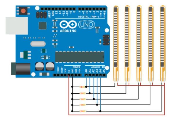
The flex sensors require a circuit in order for them to be compatible with Arduino. It’s a voltage divider: the flex sensors are variable resistors, and when paired with resistors of a static value, change in resistance (in this case bending the sensor) can be sensed through the change in voltage between the resistors. This can be measured by the Arduino through its analog inputs. The schematic is attached (red is positive voltage, black is negative, and blue goes to the Arduino). The resistors in the photo are 22K. I color-coded the wires I used in the same way as the schematic, so you can see more easily.
The main GND wire, which is connected to all the individual GND wires from the sensors, gets plugged into the Arduino’s GND. The +5V from the Arduino goes to the main positive voltage wire, and each blue wire gets plugged into a separate analog input pin.
I soldered the circuit onto a small PCB from RadioShack, one that could be easily mounted onto the glove. I was able to solder the wires to the sensors relatively easily also, and used heat shrink to make sure there were no shorts. I then wrapped the area where the wires are connected to the sensors with electrical tape to stabilize the sensors. Near the bottom, where the leads are attached, the sensors are a bit weaker and the tape ensures that they won’t bend too far and won’t get damaged.
Step 4: Sew the Glove
Now it’s time to mount the sensors and their circuit onto the glove itself. First, drill a tiny hole in the plastic of the sensors (at the top, once the resistive material has ended). Be sure not to hit the resistive material! Then, put on the glove and pull it tightly to your hand. On each finger, with a pencil or pen, make small lines over the tops of each joint/knuckle. This will tell you where to sew the sensors. Sew each sensor tip to the area of each finger just above where each of your fingernails would be (use the hole you just drilled). Then, for each sensor, make loose loops around them with thread at both joints in each finger. Once each sensor is in place and slides under the loops of thread nicely, sew the PCB onto the wrist part of the glove tightly.
REMEMBER: for each step in this process, be sure you’re not sewing the glove itself closed. That’s quite a hassle.
For more detail: DIY Robotic Hand Controlled by a Glove and Arduino