The programmable bench power supply (PSU) is an attempt to bridge the gap between so many simple hobbyists/DIY power supplies and commercial solutions trying to combine the best ingredients and practice from both sides. The former solutions are in general open source with limited feature set and without support for some standardized way to communicate with them (e.g. SCPI). The later solutions are costly and not open (and easily “hackable”).
This is an ongoing project and our aim is to provide a solution that is comparable with commercial solutions and it’s completely open (software and hardware) that anyone can freely replicate it or use some of building blocks for making new solutions.
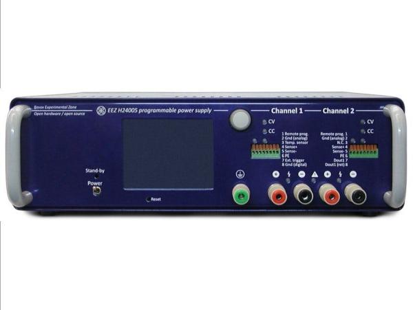
Currently we have three working prototypes. We named that latest prototype EEZ H24005 that stands for hybrid, dual channel, 40V and 5A.
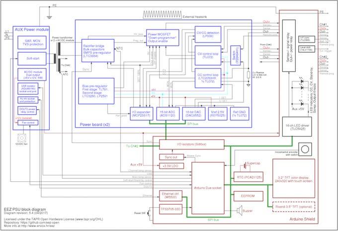
From the very start we tried to make it modular. In that way would be much easier to understand how it works, assembly and repair it. Currently it’s consist of three PCBs:
- Power module (2 is required per unit)
- Arduino shield for digital control
As an power input it’s possible to use affordable toroidal transformer with dual secondary coils or two 48 V AC/DC modules.
To further simplify it’s building we succeed to reduce number of wiring to the minimum. That is accomplished by grouping all control and output power lines to the single connector on the Power module, and two of them are directly plugged into Arduino shield that is mounted directly on the enclosure front panel and carry 3.2″ TFT color touch-screen display from one side and Arduino Due from another.
The TFT display is used as only local user interface. No additional switches, potentiometers or keypads are required. A lots of space is saved on the front panel in that way, yet it allows that all functions for both channels can be easily accomplished from the single place.

This board is used to accomplish the following:
- AC power soft-start/stand-by
- +5 V for Arduino shield supply
- carrying Ethernet and USB connectors (with option to isolate USB) and
It’s intended for mounting (with help of few metal spacers) directly on the enclosure rear panel. Dangerous mains voltage is present only on this board and it works with both 115 and 230 VAC (50/60 Hz). More details about this board can be found here.
Power Module
The power module main purpose is to provide reliably on its output regulated output voltage and current. Most of the important parameters that are usually measured to find out a power supply performance depends of this module design. The current version (r5B9) is a result of many iterations and great feedback from various people on few forums. We believe that this most challenging part of this PSU could be further improved in many ways: e.g. by lowering BOM count without necessarily decrease overall performance, decrease ripple and noise possibly with four layer PCB, etc.
Its power stage is divided in two sections: pre-regulator that is built around LTC3864 buck/step down controller and mosfet post-regulator that is based on excellent work of. This hybrid design comes with one interesting feature: low-ripple mode of operation thanks to used LCT3864 that works with P-channel mosfet and allows “100% duty cycle when the pre-regulator circuit is in fact by-passed and hard to filter switching noise is decreased on the output. Entering that mode of operation is managed by MCU and it’s in line with pre-regulator’s switching mosfet and post-regulator pass mosfet SOA.
This module also has a bias power supply that are used for powering all analog and digital controlling circuits. It provides +5 V, -5 V for op amps that are used for CV (constant voltage) and CC (constant current) control loops, +5V for digital section (ADC and 8-bit I/O expander). Additionally its provide -9V that is required for so-called “down-programmer” (DP) circuit. The DP is used to speed up output voltage programming when new set voltage is lower. The bias power supply also provides power good signal that is used to indicate MCU the “health” of the controlling circuits power.
Digital part of the module provides 16-bit programming resolution of both voltage and current using DAC8552. Currently the output resolution is firmware limited to two decimal points (10 mV, 10 mA) and leave enough room for better precision (down to 1 mV, 1 mA full scale). The ADS1120 offers 15-bit monitoring resolution of programmed (DAC outputs) and actual (post-regulator outputs) voltage and current.
The power module also has an output enable (OE) circuit. That function could be achieved by programming output voltage to zero, but in this way it’s possible to easily add a manual switch independently from MCU operation (as extra measure of precaution in case of failure).
Read More: DIY Programmable (SCPI) Bench Power Supply