Summary of DIY GPS Tracked Bike Lock using Arduino
Summary (under 100 words): An Arduino-based GPS-tracked bike alarm using a modified retractable cable lock triggers the Arduino when the lock is cut. A PNP transistor gate is held by the steel cable; cutting the cable grounds the base, powering the Arduino, which then uses a GSM shield and GPS breakout to report location. Design priorities were Arduino compatibility, compactness to fit under-seat, and multi-week battery life. Total parts cost about $225 if bought new.
Parts used in the GPS Tracked Bike Lock:
- Arduino Uno
- Arduino GSM Shield
- Adafruit Ultimate GPS Breakout
- Arduino Prototyping Shield
- PNP Transistor (TIP127 used)
- 2.7K Resistor
- 7.4V 2S Li-Po Battery Pack
- Retractable Cable Lock
- GSM SIM Card
- Under Seat Bag
- Wire
- Solder
- 5 Minute Fast Set Epoxy
- Zap Straps
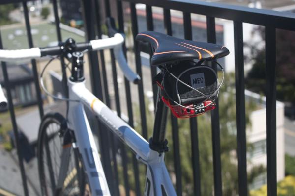
Having just purchased a half decent bicycle, and living in a city with a bike theft rate almost as high as New York, I wanted to have some peace of mind that if a thief with an angle grinder were to cut through my U-lock I could still catch them.
My main design constraints were as follows:
- The device has to be Arduino based so that if I run into trouble I can easily search the forums for help
- Whatever I make has to be able to fit into a small bag that goes under my seat
- The battery must last for a very long time, at least a few weeks. I don’t want to have to plan my bike rides around my lock being charged or not.
This project is pretty cheap, especially if you compare it to the cost of replacing your stolen bike! I’ve outlined the cost of all the components used in my design below. I was able to use some old parts I had lying around and hopefully you will too. If I had bought everything needed brand new this would have cost about $225.
Components
- Arduino Uno ($24.95) https://www.sparkfun.com/products/11021
- Arduino GSM Sheild ($99.95) http://www.amazon.com/Arduino-GSM-Shield-Integrate…
- Adafruit Ultimate GPS Breakout ($39.95) http://www.adafruit.com/product/746
- Arduino Prototyping Shield http://www.adafruit.com/products/51
- >1.5A PNP Transistor, I used the TIP127 just because it’s what our local electronics store had. I’ll go over precautions for using different transistors later. ($1.00) http://ca.mouser.com/ProductDetail/STMicroelectron…
- 2.7K Resistor ($1.00/pack)
- 7.4V 2S Li-Po Battery Pack ($10) http://www.hobbyking.com/hobbyking/store/__37346__…
- Retractable Cable Lock ($12.42) http://www.amazon.com/Master-Lock-4605D-3-Foot-Ret…
- GSM SIM Card ($10 + 30cents/sms) This is the rate on Rogers in Canada. Just make sure you are on a GSM carrier.
- Under Seat Bag ($14) for vancouverites MEC has a great one that fits everything snugly. I suggest you try fitting everything in the bag before you take the tags off. http://www.mec.ca/product/5024-801/mec-shell-seat-…
- Wire
- Solder
- 5 Minute Fast Set Epoxy ($5)
- Zap Straps ($2)
Tools
- 2S Li-Po Battery Charger
- Soldering Iron
- Wire Strippers
- Philips Head Screwdriver
- Flat head screwdriver (or some other good prying tool)
- Digital Multimeter
Step 1: PNP Transistor Circuit
The transistor is a device that is used for switching. A very small input can enable a very large current output. In the case of the TIP127, it can handle 5 amps and has a gain of 1000. Roughly this means that if you were to need to drive 5 amps your effective input would need to be 5/1000 amps.
http://www.electronics-tutorials.ws/transistor/tra…
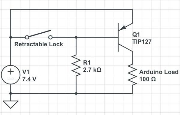
The PNP transistor is “off” when you connect the base to the positive side of your circuit and on when it is connected to ground.
The way it is used in the bike lock is pretty clever I think, the steel cable of the lock will connect the positive side of the circuit to the base of the transistor. When the lock is cut, the connection is broken and the path of least resistance will be to ground. When the base is grounded like this power is supplied to the Arduino
This is the clever part of this design. It means that we will only be using full power power during the small amount of time it takes to lockup your bike. The rest of the time it will only be using the small amount of power used to supply the transistor.
Test out your transistor circuit on a breadboard before soldering to your Arduino prototyping shield. While testing your circuit use a switch in place of the retractable lock in the next step. With the TIP127 hook the circuit as per the schematic above. If you want to use a different transistor than the TIP127 the only thing that will change is the value for R1.
Step 2: Modifying the Retractable Lock
We need the retractable lock to serve as an electrical connection from the positive side of the battery to the base of the transistor. This way when the lock is cut, the electrical connection is cut as well and the Arduino will boot up.
Assuming that you have the lock that I recommended in the intro, the first thing is to remove the screw that connects the two halves of the plastic case. The use a wedge to pry open the edges and separate the two halves.
At this point it is a good idea to take a picture of the inside of the lock so that if any pieces fall out you can put them back later. I forgot to do this which resulted in a lot of wasted time studying the mechanism.
Time to get out the soldering iron. Make one connection for a wire on the brass ending of the steel cable. It is located on the spool the the cable wraps on when inside the lock. Make the second connection on the spring that holds the pin that the cable makes contact with when you insert it into the lock. Use your DMM to check for conductivity when the cable is inserted into it’s hole and that there is no conductivity when it’s lose. A lose cable is the same effect as cutting the lock.
Make one hole in the plastic case near your spring connection. The other hole should be made halfway between the centre of the spool at the bottom and the outer edge of the spool. I found that making a connection in the centre of the spool would twist the wire so much that it would break.
Congratulations if you’ve made it this far the hardest part it over! Lastly just run your two wires through the holes you’ve made and close up the case. If you’re finding that the screw is not enough to hold the two halves together anymore a generous coating of epoxy resin is recommended. Also, depending on what type of bag you will use for the electronics it may be useful to put the screw through a zap strap so that you have a way of securing it to the bag. Put some epoxy on the zap strap as well. Just don’t be too generous or you may gum up some of the important mechanisms of the lock. During this step I managed to glue the retracting mechanism of my lock so be very careful. Clamp your lock together and leave it for at least an hour.
Step 3: Add GPS
The ultimate GPS breakout from adafruit works well in this application. Hooking it up couldn’t be easier. Find a good place for it on your pro to shield and then just connect the Vin to 5V, GND to GND, Rx to digital 9, and Tx to digital 8.
This is all you need to get the GPS working however adafruit has nicely broken out Vbat so you can supply 3.3V to the GPS’s internal clock when the power is off. This will give you quicker startup times. I used one of my LiPo cells to supply this with 3.7V. This can in theory discharge both LiPo’s unevenly and be dangerous, however considering the power used it very small I think the uneven discharge rate will not be a problem. And so far so good, if i have a spectacular problem with respect to this I will be sure to post it here.
For more detail: DIY GPS Tracked Bike Lock using Arduino
- How does the lock detect being cut?
The steel cable connects battery positive to the transistor base; when the cable is cut the base is grounded and the Arduino powers up. - Can I use a different PNP transistor?
Yes; only the value for R1 will change if you use a different PNP transistor than the TIP127. - What GPS module is used and how is it connected?
The Adafruit Ultimate GPS Breakout is used; Vin to 5V, GND to GND, Rx to digital 9, and Tx to digital 8. - How is long battery life achieved?
The design keeps the Arduino off until the lock is cut by using the transistor switch, so only small standby current is used most of the time. - Do I need a GSM SIM card?
Yes; a GSM SIM card is required for the Arduino GSM Shield to send messages, and the author used a GSM carrier. - How are wires connected inside the retractable lock?
A wire is soldered to the brass end of the steel cable spool and another to the spring that contacts the cable pin, then routed through holes in the case. - Will supplying Vbat speed up GPS startup?
Yes; supplying 3.3V to Vbat preserves the GPS internal clock for quicker startup, which the author powered from one LiPo cell. - How should the modified lock case be reassembled?
Close the case, optionally epoxy if screw is insufficient, secure with a zap strap through the screw, and clamp for at least an hour to cure.