Summary of DIY Fingerprint Lock Box
This article details a DIY project to build a fingerprint-secured lock box using an Arduino UNO, fingerprint sensor, and solenoid lock. The creators designed the box in CAD software, laser-cut it from birch wood with finger joints, and 3D printed a locking mechanism. The guide covers wiring components, installing the Adafruit Fingerprint Library, programming the Arduino to recognize fingerprints and activate the lock, and assembling the portable unit powered by a 12V lithium-ion battery.
Parts used in the DIY Fingerprint Lock Box:
- Arduino UNO
- Fingerprint Sensor (from Adafruit)
- Solenoid Lock
- Jumper Cables
- One Channel Relay Module
- Breadboard
- Rechargeable 12V Lithium Ion Battery Pack
- Male-to-male DC power cable
- 2 Hinges
- 4 M3x8 screws
- 2-10 M3x12 screws
- Arduino USB cable
- DC Power Jack Plug Adapter
- Wood glue
- Laser Cutter
- Wire Cutters
- Wire Strippers
- Dial/Digital Calipers
- CAD Software
- 3D printer
- Soldering iron and solder
Ever wanted a box that opens in a super cool way? We thought it would be fun to create a box that can be unlocked using the correct fingerprint! If we had more time, we would make the box more secure. In the mean time, we have learned a lot and had a lot of fun.
We found several tutorials online that inspired us to make this awesome project:
How to Set Up Fingerprint Sensor With Arduino
Techatronic Arduino fingerprint security lock
DIY Fingerprint Door lock System
Although this project is recommended for the beginner to intermediate level, we personally found several parts of it very challenging, and hope this Instructable will help others have an easier time than we did. We built this project as part of Ms. Berbawy’s Principles of Engineering class at Irvington High School.
Supplies
Materials:
Fingerprint Sensor (from Adafruit)
Jumper Cables
Rechargeable 12V Lithium Ion Battery Pack
Male-to-male DC power cable
2 Hinges
4 M3x8 screws
2-10 M3x12 screws
Arduino USB cable
DC Power Jack Plug Adapter
Tools:
Wood glue
Adobe Illustrator/SVG editing software (Optional)
Arduino IDE
Soldering iron and solder
Laser Cutter (Optional)
Wire Cutters
Wire Strippers
Dial/Digital Calipers
CAD Software
3D printer
Screwdriver (for relay module and other electric components)
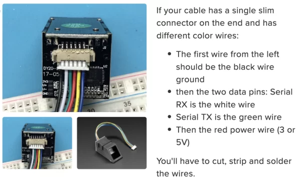
1. Attach the ribbon cable to the fingerprint sensor. Make sure the orientation of the cables is correct (refer to the image above). The only wires we will be using for the fingerprint sensor are the RX wire, TX wire, VCC (power) wire, and GND wire (refer to image).
**Note: when referring to the diagram and comparing it to your own fingerprint sensor, make sure to hold the fingerprint sensor in the same orientation as the image! (In the image above, the fingerprint sensor is upside down). You can find more information about the fingerprint sensor and what each wire corresponds to by going to this link.
2. Once you correctly attach the wire harness to the fingerprint sensor, remove the JST connector on the other hand and strip the wires. Do the same thing for the solenoid wire: Remove the JST connector and strip the wires.
3. Since the wires of the fingerprint sensor and solenoid lock are stranded, we recommend soldering solid wires to each stranded wire and adding heat shrink (to help with connections).
4. Connect all the wires and components as per the circuit schematic above.
Step 2: Code for Fingerprint Sensor
1. Download the Arduino IDE (if you don’t already have it installed) from this link.
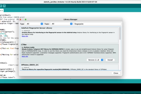
2. Download the Adafruit Fingerprint Library from GitHub: Adafruit Fingerprint Sensor Library.
3. Then in the Arduino IDE go to Tools –> Manage Libraries. Look up the Adafruit Fingerprint Sensor Library and install it.
4. Most of the code is already included in the library. To access the code to enroll the fingerprints, go to File –> Examples –> Adafruit Fingerprint Sensor Library –> enroll. This will open up the code to enroll the fingerprints.
5. Connect the Arduino to your computer and make sure that you are using the correct port. (You can check this by going to Tools –> Port.) Also, make sure you are boarding the correct Arduino by going to Tools –> Board. Then compile the code and upload it onto the Arduino.
6. To enroll your fingerprints, go to the Serial Monitor (Tools –> Serial Monitor). It will prompt you to enter an ID from 1 to 127. Type in whichever ID you want your fingerprint to have and press “send”. Then follow the instructions in the Serial Monitor to correctly enroll your fingerprint. (You will need to place your finger on the sensor twice). You can enroll 127 fingerprints; however, if you type in the same index again for a different fingerprint image, the previous one will be overridden.
**Note: If you see the message “Did not find fingerprint sensor :(” when you open the Serial Monitor after uploading the code, we recommend switching the RX and TX wire (without changing the code) or resetting the Arduino. Also, make sure the baud rate for the Serial Monitor is 9600.
7. In order to see whether the fingerprint sensor will recognize your fingerprint, go to File –> Examples –> Adafruit Fingerprint Sensor Library –> “fingerprint” to open a new program. Compile this program and upload it. Right now, the solenoid lock will not work but it will say that it is waiting for a valid finger. If you test out the correct fingerprint, it should display the line “Found ID #__ with confidence of ___” depending on how clear the match was.
Congratulations! The fingerprint sensor should be working now! If you are still having trouble, we recommend using this tutorial to get further clarification: Fingerprint Sensor Tutorial.
Step 3: Code for Solenoid Lock
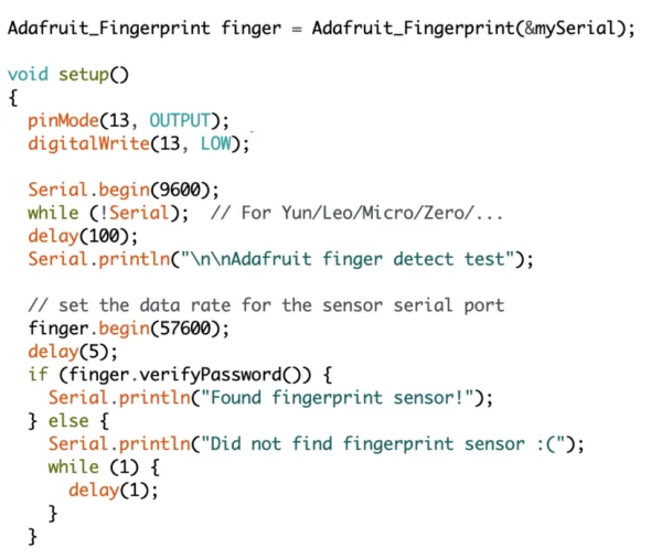
1. To activate the solenoid lock, we need to slightly modify the “fingerprint” code we used in the last step. Add the lines: “pinMode(13, OUTPUT);” and “digitalWrite(13, LOW);” right after the open curly bracket in void setup() (as shown in the image above).
2. Then add the lines “digitalWrite(13, HIGH);” “delay(3000);” and “digitalWrite(13, LOW);” at the end of the program right before the comment that says “// found a match!” (as shown in the image above). You can change the delay to whatever value you desire: It changes the amount of time the solenoid lock will be activated (unlocked).
3. Plug in the power adapter to a power outlet and to the DC power jack plug adaptor.
4. Upload the code again, and this time when the program recognizes your fingerprint, the lock should also be activated!
**Note: If your circuit is not working properly, we recommend using a multimeter to confirm that all the connections are fine and to help trace where the issue is arising (if it is a hardware problem).
5. Since we plan on using this circuit to create a fingerprint lock box, we needed to make our electronics portable, so we replaced the power source with a lithium-ion battery pack with 12V. We used this to power both the Arduino and the solenoid lock.
6. We also soldered together the three wires that were connected to the breadboard and then put heat shrink on it (since the breadboard was not necessary).
Step 4: CAD Model for Fingerprint Lock Box
At this point, the electronics should be working properly. Sometimes, if the code suddenly stops working, we recommend resetting the Arduino and going through parts of the code steps again (this happened to us frequently).
While this step is not completely necessary, we highly recommend making a CAD model for the box and adding all the components as well, just so you can get an idea of how everything will fit before laser cutting the box that will house all the electronic components. You can probably skip parts of this step if you are simply using a pre-made box. The dimensions and design of the box are completely up to you! (Refer to the images above to understand our design.)
1. We created a simple 10 in. x 4 in. x 4 in. box on OnShape (any other CAD software is also perfectly fine although the steps may be slightly different) to have a rough idea of where all of the parts would be mounted inside the box. Make sure to also keep into account the thickness of the wood you will use for laser-cutting (for example, we were using 1/8 in. birch wood, so we made the thickness of each wall 1/8 in. in our model).
2. After creating the basic box, we found online CAD versions of our specific electronic parts on Grab CAD and imported them into OnShape. In an assembly, we placed them where we wanted them to be placed using a mate connector feature.
**Note: Some of the GrabCAD models are not 100% accurate. Make sure to measure your actual components thoroughly so that you are aware of the differences between the model and the actual part. Design your box based on the actual parts and not solely based on the CAD models.
3. We wanted to have the electronics on one side of the box and we wanted space to put actual things inside the box on the other side of the box (which is why we made it so long). We added a wall between the electronics section and the empty area. Moreover, in order to save space, we originally planned to screw the relay module and the Arduino UNO to the walls of the box (as shown in the image above); however, when we actually built the box and added all the electronics, we decided that it was better for us to not screw in the Arduino (which is why there are 4 holes in the front of our final box).
4. When designing the box, make sure to accurately place any holes for screws and to size them correctly based on the size of the screw you are going to use (for example, we used M3x12 screws for everything except the solenoid lock which we used M3x8 screws for). Add holes for where the wires from the fingerprint sensor and solenoid lock will go (if you’re following a similar design to ours). If the GrabCAD model is identical to your actual component, you can make it easier to place the holes for the screws by going to the assembly in OnShape –> right-click on the part –> Edit in Context. This makes it easier to edit the box in the parts studio while being able to see the actual size of the component.
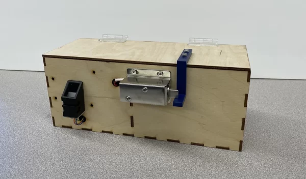
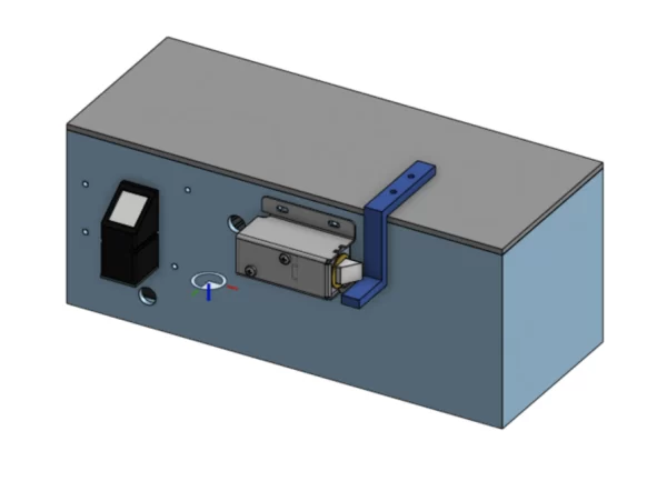
Step 5: Design the Mechanism to Lock the Box
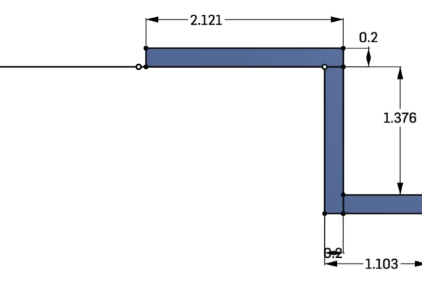
Now we had to design a mechanism that would actually keep the box locked when the lock was not activated. We wanted to place the solenoid lock sideways on the front wall and design/3D print a piece that would attach to the lid, hang over the front wall of the box, and then go underneath the deadbolt of the solenoid lock (in an “S” shape) (refer to the images above). We created a lid for the box and added holes for the screws that went through the plastic piece and also through the lid.
In the assembly, we placed the part in the correct spot on the box based on where we were planning on placing the lock and based on the lock’s dimensions. **Note: This placement is very important for the box to function correctly; therefore, be very careful about the measurements and calculations and where you place the mate connector.
Step 6: Adding Finger Joints on the Box
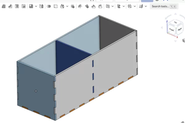
In order to make the pieces of laser-cut wood join together well when we glue them together, we used finger joints. Our original model (which had all the electronic components) had smooth edges, so we decided to create a new parts studio where we would only create the basic box with fingers.
We made the dimensions identical to the previous model. We created 0.59-inch fingers down the edge and the bottom of the box. The size of the fingers is completely up to you! **Note: Make sure that each side of the box is a separate part so that you can add the finger joints. It won’t work if the box is one single part.
We did this part manually but it can also be done by box-making software like MakerCase. If you use MakerCase, make sure to specify that the dimensions are for the outside, specify the thickness of the wood you will be using (for us it was 1/8 in. birch wood), make it an open box, and add finger joints. (We recommend making it an open box because we wanted the lid to have smooth edges and not fit into the top using finger joints since we wanted the lid to lift up when we added hinges to the back of the box.)
We chose to make the fingers manually because we also wanted to create fingers for the wall in the middle of the box that would separate the electronics section from the empty space section (refer to the images above).
Since we had already added all the electronic components and placed them in the right spots in the last step, we did not do it again for this new box.
Step 7: Laser-cutting the Box
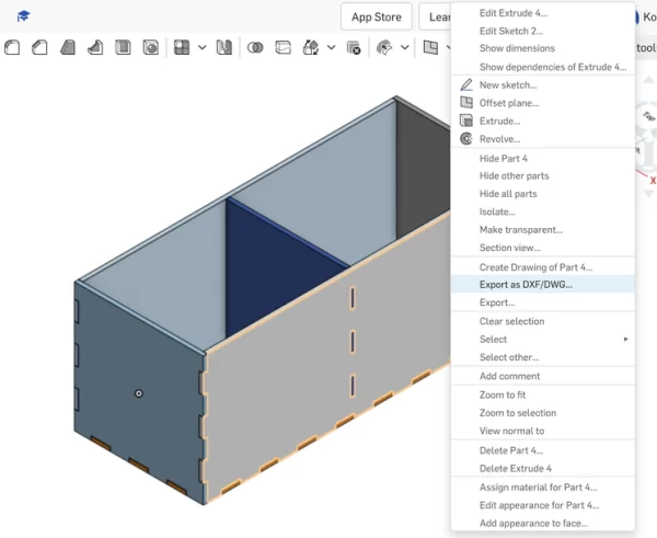
When everything is completely finalized in your CAD software, we need to export each side of the box (with fingers) individually as a DWG file and then import it to Adobe Illustrator so we can laser-cut the parts.
1. In order to export each side of the box with fingers, right-click on the part –> Export as DXF/DWG –> Export. Make sure to click on the outside of each part.
2. Open Adobe Illustrator and create a new artboard that has the dimensions of your laser cutter (for us, Ms. Berbawy’s laser-cutter is 12 in x 24 in). Make sure to change the dimensions of the artboard to inches instead of points. Then File –> Open the downloaded DWG file. When you open it, it will create a new artboard. You can add it to the artboard you already created by just copy-pasting the image. Do this for each side of the wall (create new artboards if not all the pieces fit onto just one).
3. These images only have the finger joints but they don’t have the holes for the screws and wires that we had created in the first model (where we placed all the electronic components). Since the dimensions of the box are exactly the same even with the finger joints, you can export each side of the box with the screw/wire holes and add it in Illustrator on the same artboard. You can line up this new image with the corresponding box side (which already has fingers) and then remove the outline so that you are left with all the sides of the box with fingers and with the correct placements of the screw/wire holes.
4. Once all the walls of the box are imported into illustrator, you need to adjust a few settings in order to laser cut it properly:
– Group each piece with each other (since we added the screw/wire holes after importing the original piece)
– Change the stroke color to red 255
– Change the thickness of the stroke to 0.1 inches
– Arrange all of the pieces as close together to ensure that the wood is not wasted
5. Laser-cut the pieces!
Source: DIY Fingerprint Lock Box
- How do I enroll fingerprints into the system?
You must use the Serial Monitor in the Arduino IDE, enter an ID between 1 and 127, and follow the prompts to place your finger on the sensor twice. - Can I change how long the lock stays open?
Yes, you can modify the delay value in the code to adjust the amount of time the solenoid lock remains activated. - What should I do if the sensor is not found?
If the message Did not find fingerprint sensor appears, try switching the RX and TX wires or resetting the Arduino. - Does the box require a permanent power source?
No, the project uses a rechargeable 12V Lithium Ion Battery Pack to make the electronics portable. - Is CAD modeling necessary for this project?
It is highly recommended to create a CAD model to visualize component placement before cutting the wood, though pre-made boxes can be skipped. - How are the wooden pieces joined together?
The design uses finger joints created manually or via software like MakerCase to ensure the laser-cut wood glues together well. - What software was used to design the box?
The authors used OnShape for the 3D model and Adobe Illustrator to prepare the files for the laser cutter. - Why were solid wires soldered to the stranded wires?
Soldering solid wires to the stranded wires of the sensor and lock, along with heat shrink, helps secure the connections. - How many fingerprints can be stored?
The system allows you to enroll up to 127 unique fingerprints. - What happens if I reuse an ID for a new fingerprint?
Typing in the same index again will override the previous fingerprint image associated with that ID.