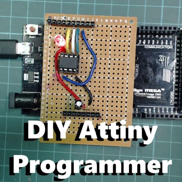
Summary of DIY Attiny Programming Shield
This article guides users in building a DIY programming shield to program Attiny85 microcontrollers using an Arduino Mega or Uno. It details the necessary components, circuit assembly on a protoboard, and specific software configuration steps for newer Arduino IDE versions, including modifying the ArduinoISP sketch and installing board manager packages.
Parts used in the Attiny Programming Shield:
- Attiny85
- Protoboard
- Male Header Pins
- 120 Piece Capacitor Set (containing a 10uF capacitor)
- IC socket
- Basic starter kit (including LED and 1K resistor)
- Mega or Uno Arduino board
- Soldering iron and wires
If you are looking for a small and low powered Arduino board the Attiny is a really good option, its surprisingly featureful for it’s size. It has 5 GPIO pins, 3 of which are Analog pins and 2 which have PWM output. It is also really flexible to the voltage that it runs off (2.7V to 5.5V) so it’s perfect for running off batteries. Did I also mention it only costs about $1!?
The trouble is with the attiny is that you can’t just plug a USB cable in to program it, but it actually isn’t hard to build a programmer for it and that is what we are going to go through in this instructable.
There are already lots of guides for building a shield, but there is a step missing when using newer versions of the Arduino IDE in the software setup in all the ones I checked that I will go through here as well.
Check out the above video where I go through all the information that is in this instructable.
Lets get to it!
Step 1: Breadboard Programmer Circuit
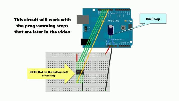
I think its worth noting that you can use a breadboard circuit to program the attiny too if you prefer to not have to build a shield. I wanted the shield so I would have something more permanent to use in the future.
If you opt for the breadboard programmer, the software steps later on are the exact same as for the shield. Skip to step 5 for this.
Step 2: What You’ll Need
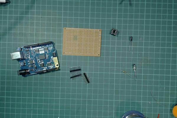
You will need the following parts to build the programmer:
Attiny85* – Probably going to need one of these 🙂
Protoboard (10 pieces)*
Male Header Pins*120 Piece Capacitor Set (has a 10uF that we need)*IC socket (20 pack)*Basic starter kit (has LED and 1K resistor that we need)*
Mega board I used* – any Mega or Uno will work though.
You will also need a soldering iron and some wires,
*= Affiliate Links
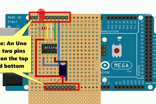
Step 3: Layout of the Shield
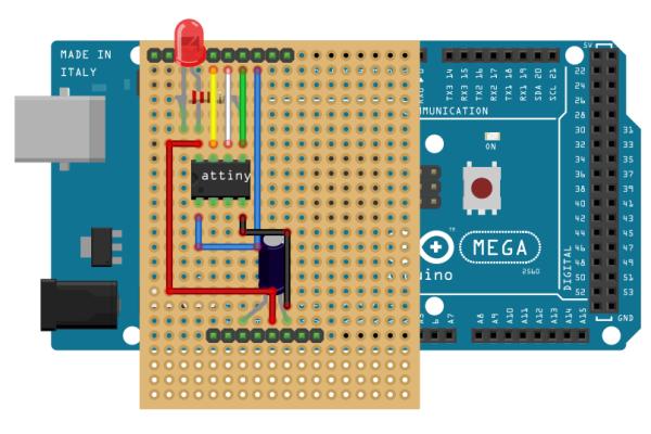
In the above images you can see the layout of the shield we are going to make. I find the image with components and wire is a little too crowded so I made up the circuit using just the wires and just the components to make it easier to read
You don’t need to use as many pins as I did, I marked in the last picture the pins that are actually needed, I just thought it would be easier to plug in the shield in the correct place if it used all the pins at the top and bottom.
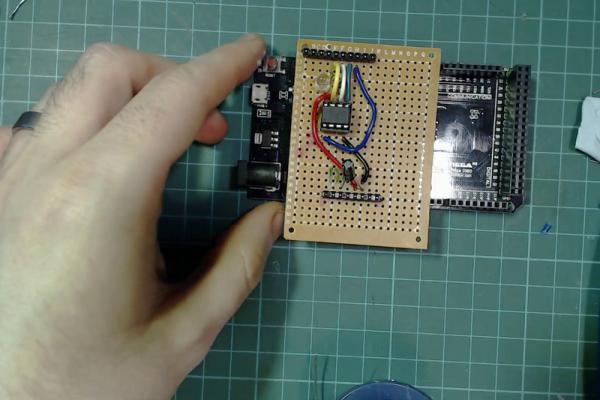
Step 4: Building the Shield
It’s a pretty straight forward circuit to build, the most complicated part is probably just getting the pins right.
The way I did the pins was:
- Cut the male header pins so they would fit in the top and bottom rows of your Mega/Uno.
- Insert them into the Arduino.
- Place the protoboard on top and mark them using a sharpie.
- Remove the headers from the arduino.
- Push the plastic of the headers to one end of the pins (I used the protoboard for this, just pushed it towards the table). They should end up looking like the pins in the picture above
- Put the pins in through the top of the protoboard (plastic on top)
- Solder them in place , solder only enough to hold in place for the moment.
After that it’s just a case of building the circuit, insert your components through and bend the pins towards where you need to connect them to and solder the connections together. I like to use blue tack to hold my components in place when I’m soldering. I’ve included a finished picture of the bottom of my board to show what mine looks like.
Make sure to double check the direction of the LED and Capacitor before soldering it up. For the LED the resistor should be connected to the short led of the LED. For the capacitor the leg with the silver marking above it should be connected to ground.
Finally it is probably a good idea to give yourself some marking or hint to remind you of the orientation of the Attiny when plugging it in. If you check the last image above I show a picture of me marking the bottom left corner, this to match up with the dot on the attiny.
If you have a multi meter, I would suggest testing the pins for any bridges between, especially the bottom pins as they are the power pins
Step 5: Setting Up Your Programmer
In order to use our Arduino as a programmer we first need to flash a sketch to it.
First plug in your shield to your arduino, they plug in the USB cable into your arduino.
Open the Arduino IDE, then click File -> Examples -> 11.ArduinoISP -> ArduinoISP
We need to make a change to this file, this is the part I found missing from all the other guides.
Scroll down on this file till you see a commented out line // #define USE_OLD_STYLE_WIRING
Remove the comment from this line (so it should now look like #define USE_OLD_STYLE_WIRING)
You can now upload this sketch to your arduino like you would any other sketch.
Step 6: Setting Up the Arduino IDE for the Attiny
We need to install the Attiny software through the board manager before we can program to the Attiny
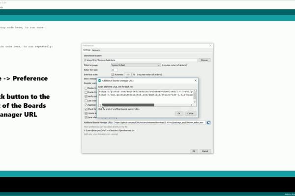
First thing we need to do is add a new line to our Additional Boards Manager URLs which can be found under File -> Preferences
The URL you need to add is:
Click the button to the right of the Boards Manager URL box and enter the above on a new line.
You now want to open the Boards Manager, go to Tools -> Board: “whatever is selected” -> Boards Manager
Search for “attiny” and click install.
Source: DIY Attiny Programming Shield
- Can I use a breadboard instead of building a shield?
Yes, you can use a breadboard circuit to program the attiny, but the software steps remain the same. - What is the best way to handle male header pins during assembly?
Cut them to fit the top and bottom rows of your Mega/Uno, mark their positions on the protoboard, then solder them through the board. - Does the Attiny85 support different voltage levels?
Yes, it runs flexibly between 2.7V and 5.5V, making it suitable for battery power. - How do I configure the ArduinoIDE for the Attiny?
You must add a specific URL to Additional Boards Manager URLs and install the Attiny package via the Boards Manager. - Which file needs modification in the Arduino IDE before uploading?
You need to open the ArduinoISP example sketch and uncomment the line // #define USE_OLD_STYLE_WIRING. - What should I check before soldering the LED and capacitor?
Verify the direction of the LED and ensure the capacitor leg with the silver marking connects to ground. - Why did the author mark the bottom left corner of the board?
The mark serves as a hint to match the orientation of the Attiny chip when plugging it into the socket. - Is testing with a multimeter recommended?
Yes, it is suggested to test for bridges between pins, especially the bottom power pins.