Summary of DIY Arduino Stepper Motor Driver Board
This article details the construction of a DIY Arduino stepper motor driver board, originally designed for heliostat and sun-tracking projects. The author notes that while commercial boards are now cheaper, this project remains a viable learning exercise. The circuit uses four Arduino pins per board to control motor coils and includes provisions for power shutdown via relays. Essential components include resistors, diodes, power transistors, heat sinks, and a protoboard. A single large protoboard can be cut to build multiple units.
Parts used in the Arduino Stepper Motor Driver Board:
- Resistors (1 Kilohms Carbon Film)
- Diodes (1 A MAX)
- Transistors (NPN Power Transistor)
- Heat Sinks (TO-220 packages)
- Protoboard
- Arduno Pins (Digital I/O)
- Motor Power Supply
- Relays (Optional for multiple machines)
- Heat Sink Compound
This page will show you how to put together a simple stepper motor driver board that can be controlled with an Arduino. I built mine to use with my heliostat projects, but it could be used for other things too.
Update: I no longer use this driver board with my sun tracking / heliostat system. Commercial driver boards have become so cheap that it is hardly even worth bothering to build it. Additionally, this driver circuit is no longer supported by the Arduino Sun Tracking / Heliostat Program. It simply uses up too many pins which are required for other features of the program.
You will need to build two of these if you are also building a heliostat or sun tracking machine, one for the altitude rotation and another for the azimuth rotation.
This stepper motor driver board uses four of the Arduino’s pins. Through some electronics trickery, it is technically possible to reduce the number down to two pins (Check out this link if your interested in doing this); however, I don’t think it’s possible to completely turn off the power to the stepper motors using this method. Since I need to be able to shut the power off, I stick with the method that uses four pins.
Parts List
Here is the parts list for the driver board. I put a link to Allied Electronics for each item with the product description in case you want to find it on another site.
This is exactly what I used, but it is, of course, possible to substitute slightly different parts for everything.
It only costs around 6 dollars for each driver board, so it isn’t a bad idea to get enough parts to build an extra one or two in case you mess something up.
For each driver board you build, you will need four of each of the items listed below.
Resistors http://www.alliedelec.com/search/productdetail.aspx?SKU=2964741
Resistor; Carbon Film; Res 1 Kilohms; Pwr-Rtg 0.25 W; Tol 5%; Axial; Cer-Core
Diodes http://www.alliedelec.com/search/productdetail.aspx?SKU=2660003
DIODE; 1 A (MAX.) @ 25C IF; 1.1 V (MAX.) @ 25C; 5 UADC (MAX.) @ 25C IR
Transistors http://www.alliedelec.com/search/productdetail.aspx?SKU=2482050
TRANSISTOR, POWER; NPN; 100VCE; 100VCB; 5VEB; 8A ICC; 1A IB; 80 W @ <= 25 C
Heat Sinks http://www.alliedelec.com/search/productdetail.aspx?SKU=6195071
Heat Sink; 1.750 in.; 0.500 in.; TO-220 packages
This protoboard is large enough to be cut up into three smaller pieces, each big enough for one driver board, so you really only need one.
Protoboard http://www.alliedelec.com/search/productdetail.aspx?SKU=2370112
Motor Power Supply
The power supply I’m using is one that came off of some unknown, obsolete household gadget, so I don’t have a link for it. Use what you think is best for your stepper motors.
Schematic
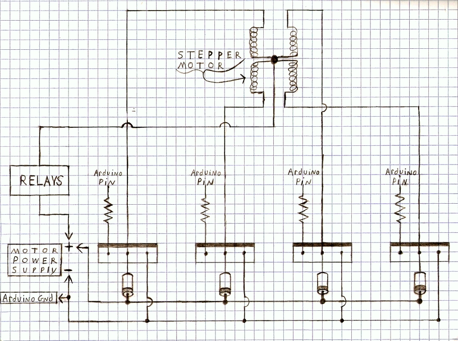
Here is the “schematic” for the circuit. I tried to make it easy to follow by drawing it to look more or less the same as it does in real life. It’s a pretty simple circuit since it is basically just the same thing done four times for each of the stepper motors coils. (Click the picture for a larger image)
Where it says “Arduino Pin” in the circuit, I use pins 2,3,4,5 for the first stepper motor (altitude) and pins 6,7,8,9 for the second stepper motor (azimuth).
Both the first and second driver board use the same motor power supply, so the positive and negative wires for each individual driver board go to the same spot.
The box labeled “Relays” is explained in more detail on the Using Relays to Control Multiple Solar Machines page. For now though, just skip it and connect the wire straight into the stepper motor’s power supply. You can come back to it later after you’re sure you have the driver board working.
I didn’t show them in this schematic (it is in the relay schematic though), but the stepper motors require a diode on each of the wires that go to the transistors if you are controlling multiple stepper motors with the relays.
If you are only going to build one sun tracking or heliostat machine, you can completely forget about the “Relays” box and diodes.
Transistor
Here is a picture showing which leads are which for the transistor in the above schematic. The smaller sized transistors use a different ordering for the base, collector, and emitter. Something to keep in mind if you were to try and modify the schematic for smaller stepper motors.
Pictures of the Build
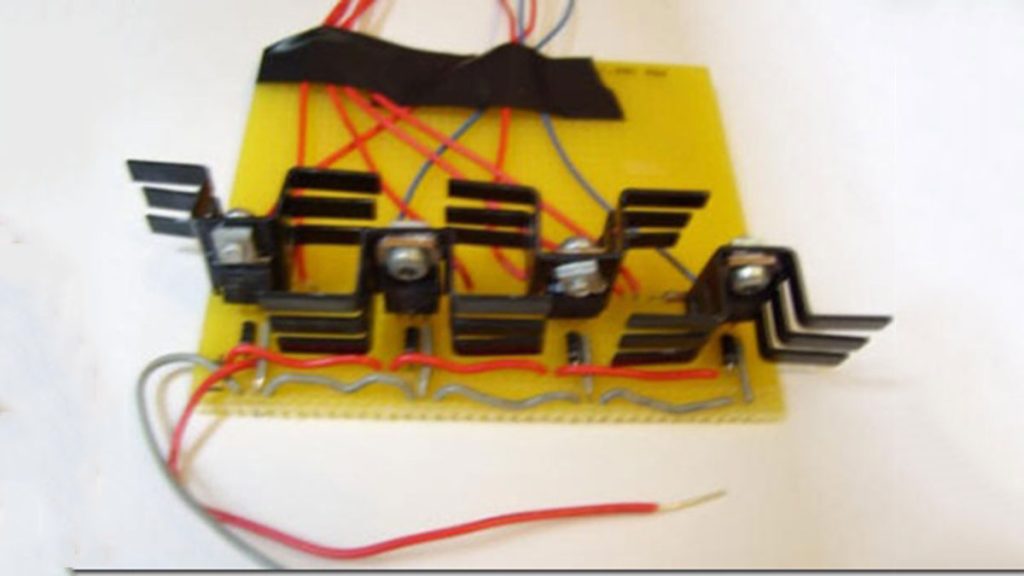
Here is a picture of one of my driver boards when it was about 3/4 finished. You can see how the positive and negative wires are laid out in this one. When spacing the transistors, don’t forget to leave room for the heat sinks.
Here is another picture of the driver board almost finished. The resistors have been added along with eight wires. The four grey wires go to the Arduino pins while the blue and red wires power the stepper motor.
This picture shows the driver board after the heat sinks were added. They are held on with nuts and bolts that I had from an old Erector set. It’s a good idea to use the heat sinks in order to help keep the transistors from getting too hot. The transistors on my board stay below 100 degrees Fahrenheit with the heat sinks attached. I also used some heat sink compound, but it might not have been absolutely necessary.
For more detail: DIY Arduino Stepper Motor Driver Board
- How many driver boards are needed for a heliostat?
You will need to build two driver boards, one for altitude rotation and another for azimuth rotation. - Can the number of Arduino pins be reduced to two?
It is technically possible to reduce the pins to two using electronics trickery, but you cannot completely turn off the power to the motors with that method. - Why does the author prefer using four pins?
The author sticks with the four-pin method because it allows for the ability to shut the power off to the stepper motors. - What is the estimated cost for each driver board?
Each driver board costs around 6 dollars. - How many of each component item are needed per board?
You will need four of each item listed below for every single driver board you build. - Do I need a separate protoboard for each driver?
No, one large protoboard is sufficient as it can be cut up into three smaller pieces for multiple driver boards. - Are relays required if building only one machine?
If you are only going to build one sun tracking or heliostat machine, you can forget about the relays box and diodes. - What temperature do the transistors reach with heat sinks?
The transistors stay below 100 degrees Fahrenheit with the heat sinks attached.