Summary of Build A Giant LED bar graph Using Arduino
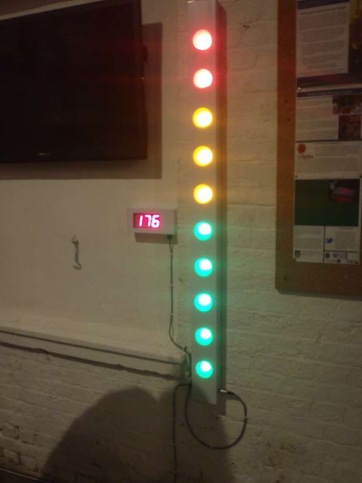
This article details the construction of a large, low-cost LED bar graph display powered by a bicycle generator. Standing 1.5m tall, the project uses electrical trunking for the enclosure and 10x 12V LED units to visualize power output. Controlled via an Arduino using shift registers, the design is robust, bright, and easily extendable.
Parts used in the Giant LED Bar Graph:
- Electrical trunking 100mm x 50mm in 2m lengths
- End caps for the trunking
- Frosted polypropylene sheet
- 12V LED units (9 super flux LEDs each)
- 3mm Machine screws 20mm long
- 3mm locknuts
- Wire
- Glue or hot melt glue gun
- 74HC595 Shift register
- ULN2003 NPN Darlington transistor array
- 0.1uF capacitor
- 100uF capacitor
- Strip board (Veroboard)
Here I show the process of building one. This one has 10 light elements, but can easily be extended to suit your idea.
It is designed to be controlled using an Arduino development board, but uses logic shift registers, so can be easily controlled by any microcontroller.The video here shows the unit in action.
The main body is built from electrical trunking, which is available in 2 and 3m sections. This forms a relatively cheap, robust and long enclosure.
The LED light units are 12V DC units from Phenoptix. The PCB was designed by Big Clive and is designed to fit into a standard MR16-type 12V halogen light fitting. They are available in all
Step 1: Parts and tools required
Parts required:
Electrical trunking 100mm x 50mm in 2m lengths.
I got mine from Screwfix (http://www.screwfix.com/p/maxi-trunking-100mm-x-50mm-x-2m-pack-of-6/99297) but its available in all electrical supply places
2 x End caps for the trunking
Again from Screwfix (http://www.screwfix.com/p/tower-end-cap-100-x-50mm-pack-of-2/46339)
Sheet of ‘frosted’ polypropolyene
I got mine from Paperchase, but you can use thin card or plastic from milk bottles or other stuff here.
10 x 12V LED units.
These were designed by Big Clive (http://www.bigclive.com/) and obtained from Phenoptix (http://www.phenoptix.com/) and have 9 x ‘super flux’ LEDs on them.
I used 5 green, 3 yellow, 2 red to give an indication of power level.
3mm Machine screws 20mm long
3mm locknuts
Wire
Glue – hot melt glue gun would work, or any general purpose glue.
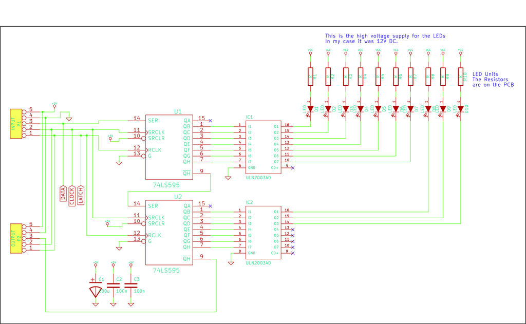
Control circuit:
74HC595 Shift register (http://www.nxp.com/documents/data_sheet/74HC_HCT595.pdf)
ULN2003 NPN Darligton transistor array (http://www.datasheetcatalog.org/datasheets/120/489337_DS.pdf)
0.1uF capacitor
100uF capacitor
Piece of strip board (also called Veroboard)
When I built mine the total cost of parts was around £100 (including £60 for the LEDs, £20 for the trunking, £5 for the end caps).
Tools:
58mm hole saw
Hacksaw for plastic
3mm drill bit
Drill
Soldering iron and solder
Screwdriver
Pliers
Strip-board cutter (to cut the tracks in the stripboard – you can also use a drill bit to do this)
Step 2: Build the enclosure
Mark out distances between light elements. I used 130mm between the middle of each light unit. I used 150mm on each end, which made a total length of 1470mm.
Cut trunking to length with hacksaw. Ensure ends are cut straight.
Drill pilot hole for each light element. This ensures they are all in a stright line.
Cut the 10 x holes for the light elements using the hole saw.
Stick the ends onto the trunking
Cut ‘frosted’ plastic to fit the holes. It needs to be just larger than the holes so you have a surface to stick to.
You will need 10 of these, one for each hole. Glue them in place and leave to dry.
Step 3: Build the LED boards
The LED kits are available from Phenoptix (click on this link).
They contain 9 super flux LEDs (which have 4 pins) and 4 x resistors.
I was using single colour ones hence all the LEDs and resistors were th same for each board.
Its pretty simple to solder them up but soldering all 10 of them takes a bit of time and some fumes.
The PCB is designed as an RGB device, but I was just using single colours, hence all three inputs needed to be wired together.
The positive lead goes to each LED board. You need to solder a negative control lead to each LED board.Once you have built the LED boards, use a space PCB as a template and drill 3mm holes to hole the PCB.
I used M3 x 20mm countersunk machine screws and locknut to hold the boards in position.
For a flat finish so it will fit on the wall without scratching, use a counter-sink drill bit on the back and the countersunk machine screws will fit into the holes much better.
- How can the project be controlled?
The unit is designed to be controlled using an Arduino development board but utilizes logic shift registers so it can be easily controlled by any microcontroller. - What material is used for the main body enclosure?
The main body is built from electrical trunking available in 2 and 3m sections which forms a cheap, robust, and long enclosure. - How are the light elements spaced within the trunking?
The author used 130mm between the middle of each light unit with 150mm on each end to achieve a total length of 1470mm. - Can this design be extended beyond 10 lights?
Yes, while this specific build has 10 light elements, the design can easily be extended to suit your idea. - What type of LEDs were used for the display?
The project uses 12V DC LED units containing 9 super flux LEDs, arranged here as 5 green, 3 yellow, and 2 red to indicate power levels. - How are the LED boards mounted inside the trunking?
The boards are held in position using M3 x 20mm countersunk machine screws and locknuts drilled into the PCB. - What tools are required to cut the holes for the lights?
A 58mm hole saw is used to cut the holes for the light elements after drilling pilot holes to ensure they are in a straight line. - How much did the parts cost for this specific build?
The total cost of parts was around £100, including £60 for the LEDs, £20 for the trunking, and £5 for the end caps.