Summary of DIY ARDUINO NANO HV UPDI PROGRAMMER
Arduino released a UPDI programmer guide in May, and Dlloydev now offers a GitHub tutorial for an Arduino Nano HV UPDI programmer. This device supports three programming modes (UPDI, HV, PCHV) at 5V while preventing MCU lockout. The process involves installing megaTinyCore, removing the write protect jumper to upload firmware, then reinstalling it. Users can verify operation via LED indicators: red/yellow for programming mode, flashing blue for HV pulses, and blinking yellow for overload status below 4.5V.
Parts used in the Arduino Nano HV UPDI Programmer:
- Arduino Nano
- megaTinyCore board package
- HV Programmer Firmware
- jtag2.updi.ino sketch file
- Write Protect jumper
- Serial port connection
In May, Arduino released a guide on how you can create a UPDI programmer for under $10. Now Dlloydev has posted a guide on Github how to make an Arduino Nano HV UPDI programmer.
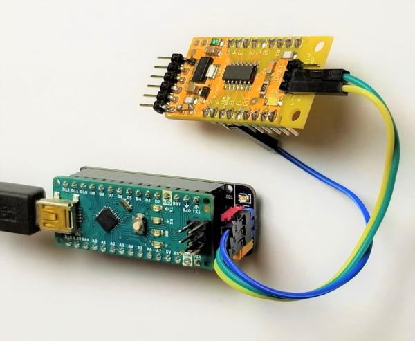
The Nano HV UPDI programmer will enable you to use the additional configuration settings for the UPDI pin without the fear of getting locked out from the MCU. The Nano HV features 3 programming modes: UPDI, HV or PCHV, with the target voltage at 5V.
To get started, you have to install megaTinyCore, then Install the HV Programmer Firmware. After installation, you click on the green “Clone or download” button, then select “Download ZIP“. When you are through with the download, you unzip the file in a folder on your PC, then load the sketch “jtag2.updi.ino” into the Arduino IDE. Note that you have to uninstall the Write Protect jumper from the programmer for you to carry on with the project, the reason for this is that with a jumper installed, the auto-reset circuit of the programmer is disabled. This protects against accidental overwriting of the firmware and also ensures quick programming sessions by eliminating extra bootloader delays that would be caused by triggering the reset. Moving forward, from the IDE, you select Tools > Board > “Arduino Nano”. Then you select Tools > Port > (serial port used by the Nano). After that, you select Sketch > Upload.
When you are through with the upload, You have to install the Write Protect jumper. Finally, from the IDE, select Tools > Programmer > “jtag2updi (megaTinyCore)”. After going through all these processes, you can now use the Nano HV programmer to “Burn Bootloader” or to “Upload Using Programmer” from the Arduino IDE. However, you have to make sure to choose the appropriate board, chip, and port setting target. Then you can choose Programmer Mode Selection you want. To know if it is programming mode, the red and yellow LEDs will be ON. On startup, the yellow LED will indicate overload status. When the programming mode is set to HV or PCHV, bright blue LED flashes to indicate the HV pulse during programming of the target. On startup, the OVL sense analog input (A6) will be checked. If the voltage on A0-A5 (target power) has dipped below 90% (4.5V), then the yellow LED will indicate overload status by blinking at 4Hz. The user will then need to correct the problem and press reset to clear.
Read more: DIY ARDUINO NANO HV UPDI PROGRAMMER
- What is the primary function of the Nano HV UPDI programmer?
It enables the use of additional configuration settings for the UPDI pin without fear of locking out the MCU. - How many programming modes does the Nano HV feature?
The Nano HV features three programming modes: UPDI, HV, and PCHV. - Why must the Write Protect jumper be removed initially?
Removing the jumper disables the auto-reset circuit protection, allowing firmware upload and eliminating extra bootloader delays. - Which sketch file should be loaded into the Arduino IDE?
You need to load the sketch named jtag2.updi.ino into the Arduino IDE. - How do you select the correct programmer in the IDE after installation?
Select Tools > Programmer > jtag2updi (megaTinyCore). - What indicates that the device is in programming mode?
The red and yellow LEDs will be ON when in programming mode. - What happens if target power dips below 90%?
The yellow LED will indicate overload status by blinking at 4Hz. - How do you know if an HV pulse is occurring during programming?
A bright blue LED flashes to indicate the HV pulse when the mode is set to HV or PCHV.