Summary of Disney Magic Band Scanner
This project details the construction of a display-only Magic Band Scanner inspired by Walt Disney World's FastPass system. Designed as a gift for Disney fans, it utilizes an Arduino Nano, RFID reader, and MP3 board to trigger synchronized LED lights and sounds when a tagged "puck" is scanned. The build involves 3D printing Mickey Mouse-shaped components, assembling custom electronics, and housing the unit in a stained wooden frame with hanging capabilities.
Parts used in the Magic Band Scanner:
- Overture PETG or Clear 3D Print Filament
- Mini USB Cable
- Arduino Nano
- 2W 8 Ohm Speaker
- MP3 Player Board (DFRobot DFPlayer Mini)
- M3 Fasteners
- Passive RFID Tags
- RFID Reader (MFRC522)
- LED Strip (144 LEDs/m)
- 22 Gauge Wire
- Solder and Soldering Paste
- Hot Glue or Super Glue
- Heat Shrink Tube
- 120 Grit Sand Paper
- 3/4 Inch Thick Wood
- Wood Stain
- Clear Gloss Coating
- Spray Paint
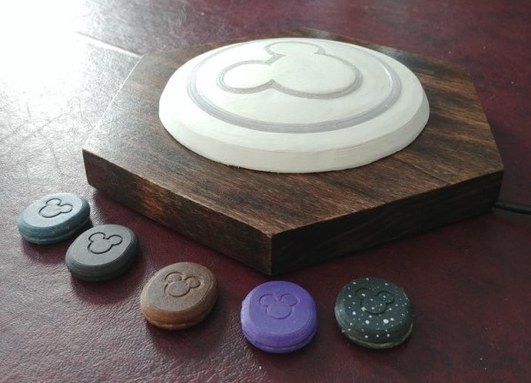
This is a Magic Band Scanner. It is inspired by the Magic Band Scanners that can be found at Walt Disney World. It is used at the entrances to all the parks and rides with the FastPass system.
I designed and built this as a present for my parents. They are huge Disney fans and have not been able to travel to any of the parks since before the pandemic. This version is for display only, but could easily be modified to control (on/off) an electronic lock or other electrical device.
Supplies
Materials
- 3D Printing Filament of your choice (I prefer Overture PETG)
- Clear 3D Print Filament
- Mini USB Cable
- Arduino Nano
- 2W 8 Ohm Speaker
- MP3 Player Board
- M3 Fasteners
- Passive RFID Tags
- RFID Reader
- LED Strip (144LEDs/m)
- Wire (22 Gauge)
- Solder
- Soldering Paste
- Hot Glue (or Super Glue)
- Heat Shrink Tube
- Sand Paper (120 grit works good)
- 3/4″ Thick Wood
- Wood Stain of your choice
- Clear Gloss Coating
- Spray Paint of your choice
Tools
- 3D Printer (I use the Prusa MK3)
- Soldering Iron
- Solder Sucker
- Wire Strippers
- Multi-meter for trouble shooting
- Hot Glue Gun
- Band Saw (Or hand saw with a lot of work)
- Router
- Key Hole Router Bit
- Drill
- Jigsaw
- Dremel
- Brush or Rag (for staining)
- Belt Sander (optional)
Step 1: 3D Print All Parts
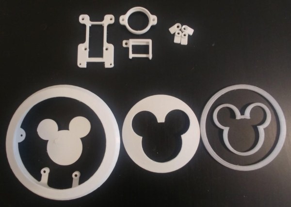
Attached, you can find all the .STL files to print. Please orient your prints so the support material is on the unseen side of the parts, this will make the sanding and finishing steps much easier.
- These were fine-tuned so there is no need for M3 nut and allows for a nice press fit of the components listed in the supply list.
- Print parts with 100% infill and 0.2mm layer height.
- For the prints that make up the front face, you can reduce the layer height to reduce sanding time.
Print List
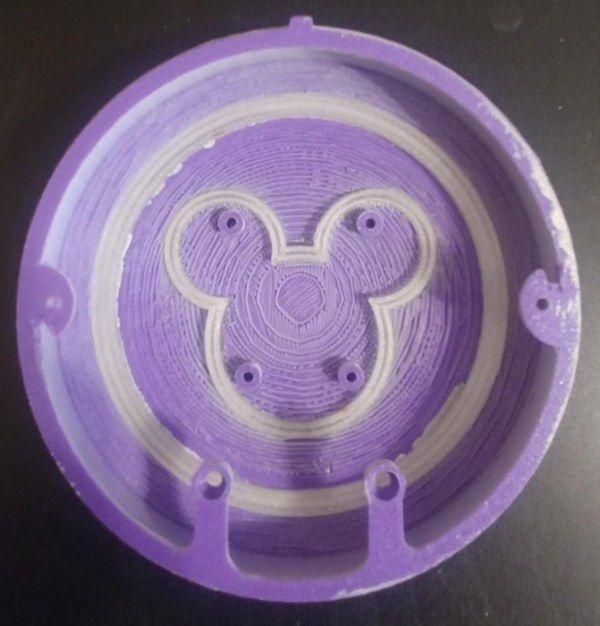
- x1 Mickey Center Face
- x1 Clear Mickey Ring (Print with clear filament)
- x1 Middle Mickey Ring
- x1 Clear Round Ring (Print with clear filament)
- x1 Outside Perimeter
- x1 Arduino Mount
- x1 Sound Board Mount
- x1 Speaker Mount
- x1 Back Cover
- x4 Back Tabs
- x1 Back Puck (Minimum)
- x1 Front Puck (Minimum)
- x1 Hexagon Scanner Template (Optional)
Step 2: Initial Assembly & Paint

- After printing all parts, do a test fit. Assemble the front face parts together, this should be a press fit and they should stay in place. Try to align the mounting holes as in the image above.
- Now, go ahead and sand the front face until it is the smoothness that you desire. I only used 120grit sand paper for mine. but, feel free to use continually finer sand paper until the desired smoothness is achieved.
- Remove the clear parts and paint the the remaining 3 prints whatever color you want using spray paint.
- let them dry while you work on the next steps.
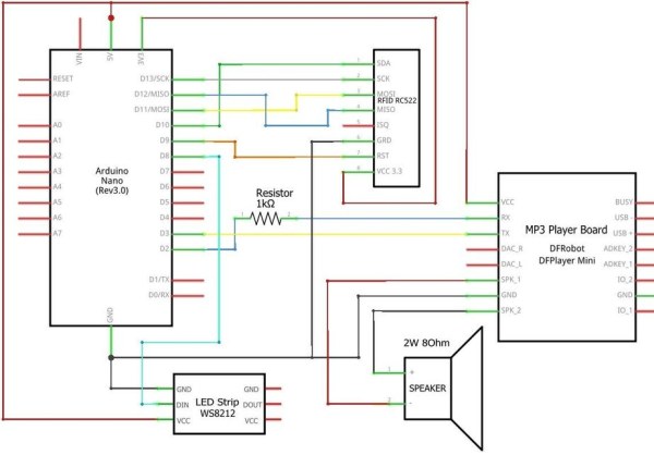
Step 3: Circuit Assembly
- (Optional) Desolder and remove all the pins from the unused side of the MP3 sound board using the solder sucker. (This helps with wire management.)
- Desolder and remove all the pins from the RFID Scanner using the solder sucker. This is important since we will want to solder directly to this board. Using the pre-installed pin connections with this PCB can cause inconsistencies in reading the RFID tags.
- Using the 22 gauge wire; cut, strip, and tin all wires needed to complete the circuit above. 6 inches is a safe length.
- (Optional) If you want to optimize the length of the wires, you can assemble the prints with the PCB’s installed and see how much wire needed to connect the pins in the final location
- Solder all connections as displayed in the circuit diagram above.
- The LED strip will need to be cut to length. a length of 54 LED’s works well. You will want a slight overlap when the LED strip is inside the 3D printed case.
- Take the micro-SD card and download the provided sound files to it, then insert it in the sound board.
- You can upload your own MP3 files to it if you want to use custom sounds too.
Step 4: Software Setup and Test

- Download the following libraries and add them to your Arduino program:
- Using the sample RFID Reader code from the downloaded library, you will be able to determine what UID (0E 48 8C B9) is set with each RFID sticker.
- Write the UID on each respective sticker so you know you put it inside the right puck.
- If you do put it inside the wrong puck, no worries, you can just change the Arduino Code to fix it.
- Using the latest version of the Arduino application upload the provided code to your Arduino Nano.
- There are a few sections of the code that contain UIDs from the RFID stickers. change them to reflect the stickers that you have.
- Test the code with each sticker and ensure it works properly.
- The sound effect is correct.
- The light display is correct.
- And they are in sync.
- If all is good you are ready to move on! If not, you will need to trouble shoot.
- Check the electrical connections with your multi-meter.
- Check the libraries are correct and working as intended.
- Check the code/UIDs are correct.
- If you are trouble shooting, I would recommend testing some sample code that came with each of the libraries and testing each subsystem separately: RFID Reader, Sound Board/Speaker, and LED Strip.
Note: The provided code is setup to allow any RFID tag “Entrance”. If you want to change it, just remove the last else {} section in the code.
Step 5: Final Assembly Prep
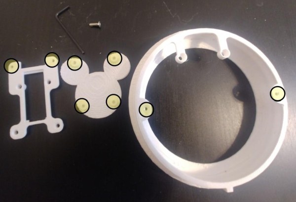
Warning: Do not overtighten screws or the print may crack or ruin the front face.
The screws can have some difficulty in catching/creating the tread in the 3D printed parts. This will make the final assembly much easier.
On the Mickey Center, Arduino Bracket, and Outside Perimeter prints use an M3 screw to tap the treads in the 8 holes called out in the image above.
Step 6: Final Assembly
Warning: Do not overtighten screws or the print may crack or ruin the front face.
- Press fit the PCB’s into their respective brackets.
- Assemble the front face.
- Insert the LED strip around the perimeter (pictured above)
- Insert x4 10mm M3 screws through the Arduino Bracket print and RFID scanner board.
- Place the RFID scanner and Arduino Bracket above the 4 mounting holes on the Mickey Center (the wires on the RFID Board should face the top of Mickeys head. Tighten the screws.
- Remove the top left screw and add the MP3 Sound Bracket to that area. Add the 10mm M3 screw there again and retighten it.
- Take the speaker and bracket and sandwich it in-between the Arduino Bracket and Outside Perimeter print. use x2 16mm screws and tighten down.
- Note: you may need to rotate the Mickey Center print to get the proper alignment so the screws can go though.
- Using hot glue (or super glue), glue the back side of the front face together. Be careful not to glue any wires to them.
- Plug in the Mini USB Cable into the Arduino Nano and bend it toward the speaker. Note: it will need to go inbetween the soldered wires on the RFID scanner.
- Carefully flatten all the cables so they will fit in the case with the back cover on.
- Place the back cover on and tighten it down using x2 M3 screws.
- Install the 4 back tabs on the back cover, leave loose enough to freely turn.
Congratulations! The majority of the project is complete. In the next steps we will make the wooden framing and RFID Puck(s).
Step 7: Wooden Frame
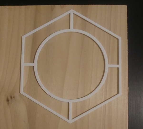
- Using the Hex Template place it on the wood of your choice and draw the inner circle and outside Hex shape. (or design whatever shape you want!)
- Cut the perimeter shape using a band saw
- Sand the corners so they are softer and slightly rounded.
- Sand the flat ends to ensure they are flat level
- Drill a few holes along the inside circle. Ensure they are big enough to allow the jigsaw an entry point.
- Using the jigsaw cut out the inner circle
- Use the Dremel, cut the top notch all the way though. This will ensure that Mickey is always facing upward.
- On the back side, use the keyhole router bit to make a spot to hang the frame. ensure this is on next to the top notch you just added.
- On the bottom side, use the router with a thinner bit to make a path for the power cable. This will ensure the frame stays flat on the wall when it is hanging.
- Stain the piece with the stain of your choice.
- for some extra protection add the clear gloss coat.
- Insert the fully assembled scanner into the wooden frame and turn the back tabs to prevent it from falling out.
Step 8: RFID Pucks
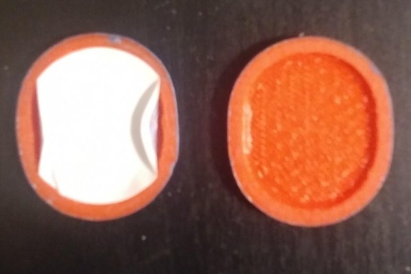
- With the front and back puck prints sand them down so they are smoother on the outside surfaces.
- place the labeled RFID sticker inside the front face. It is OK to bend the outsides of the sticker to get it to fit.
- Ensure the sticker can be read by the scanner.
- Combine the front and back halves and glue them together.
- Paint the puck with whatever pattern you want. I used a combination of spray paint and acrylic paint on mine.
- Repeat for as many pucks as you want.
Step 9: Enjoy the Show
Mount your complete Magic Band Scanner to a wall, insert one of your pucks into a magic band, tap the band and enjoy the show!
Source: Disney Magic Band Scanner
- How do I determine the UID for each RFID sticker?
Use the sample RFID Reader code from the library to identify the unique UID set on each sticker. - Can I use my own sound files instead of the provided ones?
Yes, you can upload your own MP3 files to the micro-SD card inserted in the sound board. - What is the best way to prepare the 3D printed parts for painting?
Sand the front face parts until smooth using 120 grit paper or finer, then remove clear parts before spray painting. - Does the scanner require external power during operation?
The article implies power via the Mini USB cable connected to the Arduino Nano, routed through the wooden frame. - How do I ensure the correct alignment of the Mickey Center print?
You may need to rotate the Mickey Center print so that the mounting screws align properly with the holes. - What should I do if the code does not work correctly after uploading?
Troubleshoot by checking electrical connections with a multi-meter, verifying libraries, and confirming the code UIDs match your stickers. - Can this device be modified to control an electronic lock?
Yes, while this version is for display only, it could easily be modified to control an on/off electronic lock or other device. - How many LEDs are recommended for the strip inside the case?
A length of 54 LEDs works well, requiring a slight overlap when placed inside the 3D printed case.