
Summary of Digital/Analog Clock – Arduino + PaperCraft
This article guides users in building a unique seven-segment clock inspired by Alvin Aronson, where digits slide through tubing to cast shadows for time display. The project utilizes an Arduino Uno and 28 servos controlled via an RTC module, all housed within a papercrafted frame made of cardstock and aluminum tubing. No soldering is required, making it accessible for beginners, with construction relying on double-sided tape, paperclips, and glue.
Parts used in the Seven-Segment Papercraft Clock:
- Arduino Uno
- DS1307 or RTC clock breakout
- Servo motor controller
- 28 Servos
- Cardstock
- Hobby aluminum tubing (inner and outer)
- Double sided tape
- Sticky Pads
- Paper Clip
In this instructable we will be recreating a clock inspired by Alvin Aronson’s original design. When I first saw this clock I was very impressed by how clean an elegant the design was I immediately wanted to recreate this effect.
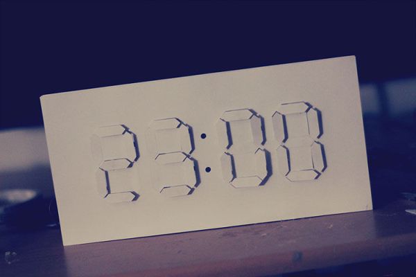
I hope some of you feel the same and use this as a guide to be one-step closer to having one of your own
Essentially, we have a seven segment clock where instead of LED’s we have digits moving in and out of the pane, the shadow created by these digits will allow the user to read the time against the white on white digits. By using 28 servos, we can use a arduino to first process the current time and then push the digits out accordingly through the motor controller. more will be explained in the later pages.
I’ve tried to keep the parts as simple as possible, using readily available parts without a deep knowledge of electronics one can begin to explore creating their own clock. I do not have 3D printer so construction will be done by way of papercrafting.
Step 1: Gather your materials
Here are the things you’ll need. I intended to fit this in the “kit contest” category so i’ve limited the build to simple parts without need for soldering. Alternatively. Arduino Uno and motor-controller can be replaces with Arduino Mega which wall allow direct control of up to 64 servos. The build costs cost me around $130 in parts. Keep in mind you can reuses the parts to create other great projects like a Hexapod!
The Electronics Kit :
Arduino Uno
DS1307 or RTC clock breakout- keeps track of time
Servo motor controller – controls servo motors
28 Servos – they rotate 180 degrees
Construction:
Cardstock
Hobby aluminum tubing* – To allow digits to slide smoothly ; need a inner and outer tube
Double sided tape
Sticky Pads
Paper Clip
*Or use a pack of cheap lead pencils
Tools:
Papercutter – Shiloutte Portrait (optional)
Glue Gun
Dremel – to cut tubing (optional)
Knife (optional)
Step 2: Test the electronic parts
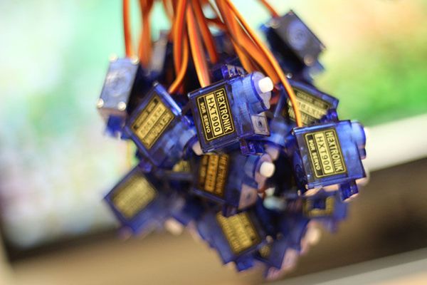
Servos
So you have a lovely ball of servos now. Better test them first. (One of mine were defective)
Connect the SSC-32 to the arduino using the attached picture as a guide
http://marc-tetrapod.blogspot.ca/2012/10/arduino-ssc-32-servo.html
RTC
What the RTC allows you to do is keep track of time using a small lithium battery. Any system [Your computer and your phone] with a clock will have one. This is the most used way to keep track of time when things are powered on/off constantly. We will hook up this circuit later on in this instructable
Step 3: Design the clock
The following pieces were designed in Adobe illustrator. With the intention of being cut onto paper. If you’re using a 3D printer you’ll likely have to use different methods but the basic idea will be the same. Also please share your designs:)
We have 6 layers:
[01] Front Face – Clock Face
[01] Front Face – Segment face
[02] Front Shield – Holds Tubing
[03] Base – Holds Servo + Tubing
[03] Base – Holds Servo + Tubing
[04] Back Shield – Holds Servo
Note: some files will need to be cut twice. see above for ordering details
Step 4: Cut out the pieces
The following pieces were designed in Adobe illustrator and cut with a Shiloutte Portrait. If you feel like you have the time you may want too cut out these layers by hand.
The metal rods were cut using a dremel. I cut the bigger tube 1cm and the one that slides inside it to 2cm
Step 5: Construction
In this step you will put the layers together using a padded double sided adhesive to construct the body. Use the images to guide you through this process
Note: Metal tubing is inserted into each segment
Step 6: Add the digits
Front Steps:
-Place inner tubing in outer tubing
-Apply Glue
-Place front facing piece
-Repeat
Back Steps:
-Cut and bend paperclip as shown in pictures
-Apply Glue
-Insert
-Bend
-Repeat
Step 7: Add the servos
Attach servos to the paperclips we added in the previous step. the frame will ensure that the servos wont slip. You may use glue if you wish.
For more detail: Digital/Analog Clock – Arduino + PaperCraft
- How does the clock display the time?
The clock uses moving digits that slide in and out of a pane; the shadow created by these digits allows the user to read the time against white on white digits. - Can I replace the Arduino Uno with another board?
Yes, an Arduino Mega can be used to allow direct control of up to 64 servos instead of using a motor controller. - What method is used for construction if a 3D printer is unavailable?
Construction is done by way of papercrafting using cardstock and other simple materials without needing a 3D printer. - Do I need soldering skills for this build?
No, the build is limited to simple parts without the need for soldering. - What software was used to design the clock layers?
The pieces were designed in Adobe Illustrator with the intention of being cut onto paper. - How are the metal rods sized for the sliding mechanism?
The bigger tube is cut to 1cm and the one that slides inside it is cut to 2cm. - How are the servos attached to the structure?
Servos are attached to paperclips added in a previous step, ensuring the frame prevents them from slipping. - What is the approximate cost of the parts?
The build costs around $130 in parts.
