Summary of DC Panel Meter using Arduino
This article details a DIY DC panel meter circuit using an Arduino Uno to display voltage and current for regulated power supplies. The system samples input via a voltage divider and an ACS712 sensor, processing data on an LCD with over-range alerts via a buzzer. It includes construction guides, PCB layouts, and safety tips like Zener diode protection.
Parts used in the DC Panel Meter:
- Arduino Uno board
- ACS712 current sensor IC
- 16×2 LCD
- BC547 NPN transistor
- Piezo buzzer
- Resistors R1 and R2
- 9V power supply
- 10W wirewound resistor
- Potmeter VR1
- 4.7V Zener diode

Panel meters in regulated power supplies are used to display electrical parameters like voltage and current. Presented here is a circuit to display DC voltage and current of power supplies, including DIY-type ones.
Circuit and working
Circuit diagram of the DC panel meter using Arduino is shown in Fig. 1. The circuit is built around Arduino Uno board (Board1), current sensor IC ACS712 (IC1), 16×2 LCD (LCD1), npn transistor BC547 (T1), piezo buzzer (PZ1) and a few other components.
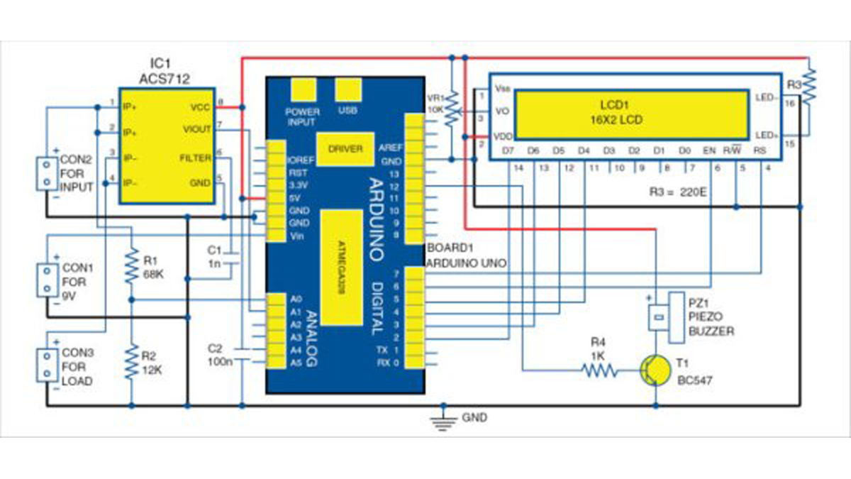
Circuit diagram of DC panel meter using Arduino
Power supply voltage is sampled using the voltage divider network built around resistors R1 and R2. Current consumed by the load is sampled using ACS712. Sampled voltage and current are given to Arduino, which is the brain of the circuit and performs calculations for displaying the parameters on the LCD1.
Voltage at Arduino analogue and digital pins should not exceed 5V. Hence, an alert message is displayed on the LCD1 and the buzzer sounds whenever sampled voltage and current go beyond the limit.
Arduino Uno
Arduino Uno is a popular open source microcontroller (MCU) development board based on ATmega328P MCU. It has 14 digital input/output (I/O) pins (of which six can be used as PWM outputs), six analogue inputs, 16MHz crystal, USB connector, power jack and ICSP header. It comes preloaded with Arduino bootloader.
ACS712
Current sensor IC ACS712 accurately detects AC or DC current, and produces analogue voltage proportional to the current passing through it. Its internal views are shown in Fig. 2. The device consists of a precise, low-offset, linear Hall circuit with a copper conduction path located near the surface of the die. Applied current flowing through the copper conduction path generates a magnetic field, which the Hall IC converts into proportional voltage. Device accuracy is optimised through the close proximity of the magnetic signal to the Hall transducer.
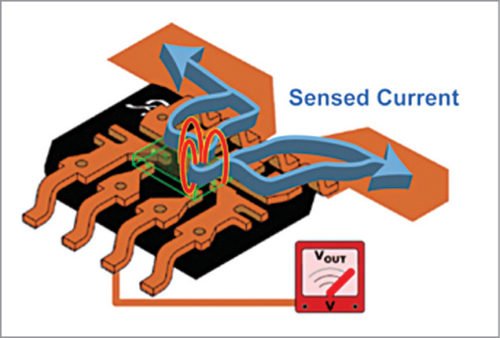
Internal view of ACS712
Output of the IC is 2.5V when no current is passed through it—it swings around 2.5V at the rate of 185mV/A for 5A version, 100mV/A for 20A version and 66mV/A for 30A version.
The graph shown in Fig. 3 shows output voltage versus sensed current of 5A version sensor IC. A readily-available 5A version sensor module is used in this circuit.
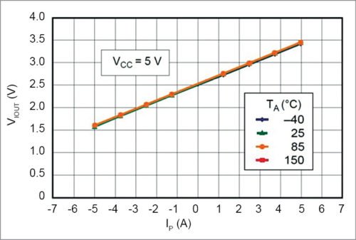
Output voltage versus sensed current of ACS712
Internal resistance of the conductive path is 1.2m, providing low power loss. Terminals of the conductive path (pins 1 to 4) are electrically-isolated from signal leads (pins 5 through 8). This allows ACS712 to be used in applications that require electrical isolation without the use of opto-isolators or any other costly isolation technique.
Software is developed on Arduino platform. After burning the code (PanelMeter.ino) into ATmega328 on Arduino Uno, remove USB power supply from the computer/laptop. Connect 9V power supply across CON1.
During testing, 5V, 5A input was used as power input source at CON1. Load connected at CON3 may have different values (ranging from 1E to 5E). A 10W wirewound resistor is used as load across CON3. Current and voltage values appear on LCD1. When current flows more than 5A, LCD1 shows over range and the buzzer produces a sound to alert the user. A low-current, disk-type piezoelectric buzzer is used.
Construction and testing
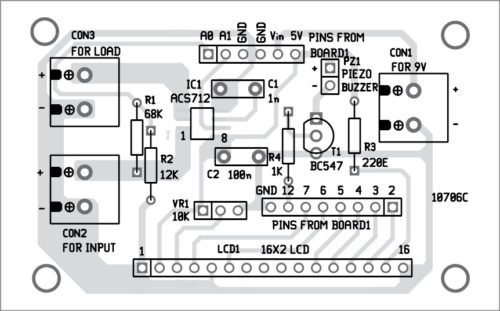
An actual-size PCB layout of the DC panel meter using Arduino is shown in Fig. 4 and its components layout in Fig. 5. After assembling the circuit on the PCB, and burning the code to the MCU, connect a 9V across CON2 to power the circuit. Connect potmeter VR1 on the front panel of the cabinet for controlling the contrast of LCD1. Connect 5V, 5A input across CON1 and load across CON3 for sensing the current.
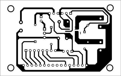
PCB layout of DC panel meter using Arduino
Components layout for the PCB
Download Source Code: click here
Use jumper wires for connecting the circuit to Arduino board. Arduino can be powered by an external 9V, 500mA adaptor or USB A-to-B cable.
If current is displayed with negative (-) sign, it either means that it is flowing in opposite direction or input pins of current sensor IC are interchanged. To use a high-current, coil-type buzzer, use a driver with external power supply instead of Arduino’s supply. For additional protection, connect 4.7V Zener diode between analogue input pins (A0 and A1) and ground of Arduino.
Read More Detail:DC Panel Meter using Arduino
- How is the voltage sampled in this circuit?
Voltage is sampled using a voltage divider network built around resistors R1 and R2. - What component detects the current consumed by the load?
The ACS712 current sensor IC accurately detects AC or DC current. - Can the Arduino analogue pins exceed 5V?
No, voltage at Arduino analogue and digital pins should not exceed 5V. - What happens when current exceeds 5A?
The LCD displays over range and the buzzer sounds to alert the user. - How can you fix a negative sign on the current display?
This indicates opposite flow direction or interchanged input pins on the current sensor IC. - Which diode provides additional protection for the analogue inputs?
A 4.7V Zener diode should be connected between analogue input pins A0 and A1 and ground. - What is the output voltage of the ACS712 when no current passes through it?
The output is 2.5V when no current is passed through the device. - How is the contrast of the LCD controlled?
A potmeter VR1 is connected on the front panel to control the LCD contrast.