Summary of CUSTOM MULTI-SEGMENT E-INK DISPLAYS FROM DESIGN TO DRIVING
This article details [upir]'s project to create custom multi-segment e-ink displays using a screen printing process by Ynvisible. The workflow involves designing vector graphics in Adobe Illustrator, sending files for manufacturing, and driving the flexible displays with an Arduino Uno R4. By utilizing the microcontroller's onboard DAC, the project achieves precise voltage control (+1.5V/-1.5V) to activate segments without extra circuitry, offering a cost-effective alternative to standard off-the-shelf displays.
Parts used in Custom Multi-Segment E-Ink Displays:
- E-ink displays
- Ynvisible (manufacturer)
- Adobe Illustrator (software)
- Arduino Uno R4
- Onboard DAC (Digital-to-Analog Converter)
- GPIO pins
With multi-segment displays, what you see available online is pretty much what you get. LEDs, LCDs, VFDs; if you want to keep your BOM at a reasonable price, you’ve pretty much got to settle for whatever some designer thinks looks good. And if the manufacturer’s aesthetic doesn’t match yours, it’s tough luck for you.
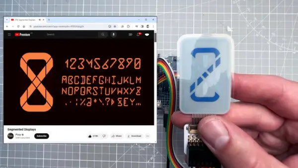
Maybe not though. [upir] has a thing for custom displays, leading him to explore custom-made e-ink displays. The displays are made by a company called Ynvisible, and while they’re not exactly giving away the unique-looking flexible displays, they seem pretty reasonably priced. Since the displays are made with a screen printing process, most of the video below concerns getting [upir]’s preferred design into files suitable for printing. He uses Adobe Illustrator for that job, turning multi-segment design ideas by YouTuber [Posy] into chunky displays. There are some design restrictions, of course, chief of which is spacing between segments. [upir] shows off some Illustrator-fu that helps automate that process, as well as a host of general vector graphics design tips and tricks.
After sending off the design files to Ynvisible and getting the flexible displays back, [upir] walks us through the details of driving them. It’s not as simple as you’d think, at least in the Arduino world; the segments need +1.5 volts with reference to the common connection to turn on, and -1.5 volts to turn off. His clever solution is to use an Arduino Uno R4 and take advantage of the onboard DAC. To turn on a segment, he connects a segment to a GPIO pin set high while sending 3.5 volts out of the DAC output into the display’s common connection. The difference between the two pins is 1.5 volts, turning the segment on. To turn it off, he drops the DAC output to 1.5 volts and drives the common GPIO pin low. Pretty clever, and no extra circuitry is required.
This isn’t the first time we’ve seen [upir] trying to jazz things up in the display department. He’s played with masking LED matrix displays with SMD stencils before, and figured out how to send custom fonts to 16×2 displays too.
Source: CUSTOM MULTI-SEGMENT E-INK DISPLAYS FROM DESIGN TO DRIVING
-
How are the custom displays manufactured?
The displays are made using a screen printing process. -
What software is used to design the display files?
Adobe Illustrator is used to turn design ideas into suitable vector graphic files. -
Which company produces these custom flexible displays?
The company called Ynvisible manufactures the custom-made e-ink displays. -
How does the author drive the segments without extra circuitry?
The author uses the Arduino Uno R4 and its onboard DAC to manage voltage levels. -
What voltage difference is required to turn on a segment?
A difference of +1.5 volts is needed between the GPIO pin and the common connection. -
How is a segment turned off in this setup?
The DAC output is dropped to 1.5 volts while the common GPIO pin is driven low. -
What is a key design restriction for these displays?
Spacing between segments is a primary design restriction during the creation process.