The Fig 1 circuit uses a Hall-effect sensor, consisting of an IC that resides in a small gap in a flux-collector toroid, to measure dc current in the range of 0 to 40A. You wrap the current-carrying wire through the toroid; the Hall voltage VH is then linearly proportional to the current (I). The current drain from VB is less than 30 mA.
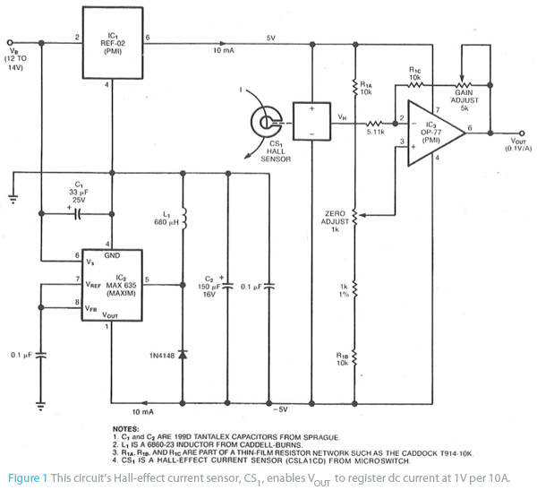
o monitor an automobile alternator’s output current, for example, connect the car’s battery between the circuit’s VB terminal and ground, and wrap one turn of wire through the toroid. (Or, you could wrap 10 turns—if they’d fit—to measure 1A full scale.) When I=0V, the current sensor’s (CS1’s) VH output equals one-half of its 10V bias voltage. Because regulators IC1 and IC2 provide a bipolar bias voltage, VH and VOUT are zero when I is zero; you can then adjust the output gain and offset to scale VOUT at 1V per 10A
ell us your most innovative and unusual idea of how you would use the R&S®Scope Rider. If your use-case is among the 10 most inspired, you’ll get the chance to show us your idea in a in a 2-minute video. 10 runners-up will each receive a GoPro camera to keep and a loan R&S®Scope Rider to create a video of their own. The best video will get to keep the R&S®Scope Rider.
For More Details: Current monitor uses Hall sensor