This project was submitted to ‘Creative Electronics’, a Beng Electronics Engineering module at University of Málaga, School of Telecommunications (https://www.uma.es/etsi-de-telecomunicacion/).
It’s a modification based on sound level meters that are already marketed for use in classes to measure ambient noise.
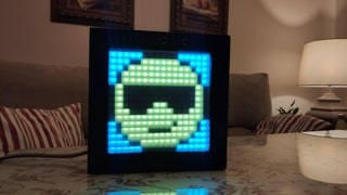
The project is developed in Arduino. It consists of a LED screen in which emoji pictures will be displayed. They will change depending on the ambient noise of the room you are in. When the noise reaches a maximum, the device beeps warning us that the noise is too loud.
It also has an option that allows you to change the brightness of the screen by turning a wheel that it incorporates. In addition, it has a frame mode, in which the emoji that appears on the screen can remain permanent, so that it does not vary with the ambient noise.
The device works plugged into the home network.
This is a simple project to do and it covers múltiple aspect such as programing, electronics, 3D print and handicraft.
This product uses a license: Creative Commons Attribution-NonCommercial 4.0 International License.
Step 1: BOM: Bill of Materials
- Wood to build the box
- 16×16 cm opaque Methacrylate
- Adafruit LED matrix of 16×16
- PCL filament
- Silicon gun
- Preamplified electronic microphone
- Switch
- Power supply
- 4k7 potentiometer
- Knob for potentiometer
- 470 Ohm resistor
- Pre-drilled board
- Tin roll
- Male – Male jumper cables for Arduino
- Male – Female jumper cables for ArduinoBuzzer pasivo
- Arduino board
- spray paint
- Power supply cable.
Step 2: Software
We have used the Adafruit_NeoPixel library made by Adafruit Industries to do this project. We applied it to control the matrix of LEDs. Also, we have used an excel file, made on the YouTube channel “Aprende y Verifica”. This file allows you to program each led of the led matrix in a more visual way. In our case, we have drawn 4 different emojis.
The code is based on a 4 state machine. Going from one state to another depends on the analog value we take from the microphone. In addition, we take an analog input value that will vary the brightness level of the screen.
In the following link to our GitHub repository you can find all the code used:
https://github.com/Creativa2021/Sonometro.git
Step 3: Making the Box
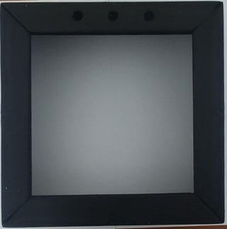
First of all, a 21.5×21.5 cm wooden box that will house all the design components has been built . We will have to leave an opening to the outside of 16x16cm, which will be where we house the methacrylate and the LED screen.
Some holes will have to be made to place the different components. As you can see, there are 3 holes in the front of the box that will house 3 microphones. This is due to a change in the design, since in the final work only one microphone is useful so it is enough to make one of these holes not three.
It will also be necessary to make holes to get the whire that feeds the system out of the box, 10 mm in diameter, another to put the switch of 18x12mm , another hole for the buzzer so that the beep can be heard better. The measurement of that hole will be the diameter of the buzzer used and finally another one to be able to manipulate the potentiometer that will allow us to change the brightness of the screen.
Step 4: Making the Grid
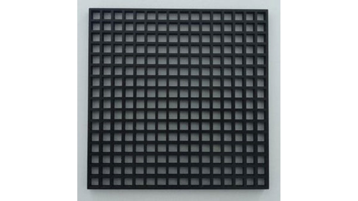
A 16.2×16.2 mm layout has been designed. In some cases, it is necessary to scale the measurements before printing, because the design may come out smaller than the actual size.
The .stl file is attached with the design so you can repeat the printing at your home.
This mesh will be placed between the methacrylate and the LED screen to create a better pixel effect. This way the colors will not mix with each other so we achive a nice effect.
Step 5: Assembly
Once the box has been builded, it will have to be painted in the chosen color.
Once the paint is dry, it’s time to begin assembly. First, the methacrylate we will be glued to the box so that it does not come loose. Next, the mesh is joined to the methacrylate, verifying that it is centered. Then, we will join the matrix of LEDs to the mesh. Once it is assembled, we will verify the correct operation to be sure any changes have to be made.
The microphone will be placed in the corresponding hole, as well as the buzzer and the potentiometer. After placing the potentiometer, the trim is screwed on it.
The Arduino board is screwed to the box, and after making the necessary connections, the power supply is also screwed.
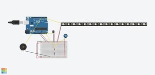
The connections of the different sensors, as well as the screen, the potentiometer and the buzzer can be seen in the photograph.
To power the circuit, a power supply has been integrated. It is important to connect the power supply well to the wire that connects to the electrical network to avoid breaking the power supply. These cables must be connected as in the attached photo. The green-yellow wire is screwed to the ground and the other two to V + and V- indistinctly.
The power supply has two 5V outputs, one of these has been used to power the led screen independently, and the other is used to power the Arduino and the rest of the sensors and actuators. To distribute the voltages and grounds we have used a pre-drilled plate, since the plate did not have the number of GND’s or 5V outputs that we needed. In turn, on this same pre-drilled board, we have soldered the resistor that forms the voltage divider with the potentiometer and we take out the analog signal that goes to the Arduino board.
Source: Creative Noise Semaphore