———————————–
*UPDATE* 3-11-10
I re-did the Eagle file and scrapped the R/C header and both of the 7805 voltage regulators. The new design will ONLY draw power from the base Arduino. There was a bit of confusion about the selectable power source of the old design, so I just made it simple. Also, it is now short enough to add an Arduino shield on top. The 2 VIN pins are to supply power to the base Arduino via it’s VIN pin (thereby powering the core2duino through the base arduino’s 5v regulator). If powered through these pins, voltage should not exceed 12v.
This design is also stackable.. meaning you can add the Core3duino on top of it!
———————————–
Using I2C, you can connect 1 Arduino (master) to a host of slave Arduino’s through Analog ports 4 and 5.
Also, you can add the security of having a completely separate CPU to your project that is unaffected by any code running on the base Arduino. I use this shield as a failsafe on my R/C lawnmower. The base processor uses the 2 external interrupts to sample and decode 2 servo signals from an R/C transmitter/receiver, while a 3rd servo signal is sent to the Core2duino that controls a relay for the motor-controller power supply. This way, even if there is a problem with the main code and it stops responding, the Core2duino will still be able to carry out it’s main function unaffected (which is to kill the power to the bot if anything unusual happens).
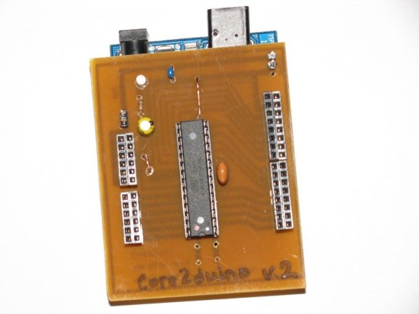
I have included the Eagle files needed to build the board. It is basically just a breakout board for the Atmega168, that has it’s own power regulation and crystal oscillator. It provides access to the base Arduino’s pins by using stackable headers that plug directly into the base Arduino.
It is a fun board to play with and I thought I would share, just in case anyone else has a use for it.
You can check out my other projects at my website: www.rediculouslygoodlooking.com
This board also works with the Core3duino… more pins!
Step 1: What you need to get started
Other things needed:
power LED, any size/color
330 ohm-1k ohm resistor for power led
10k resistor for reset button
reset button
.1uf capacitor optional
Acetone
etchant solution (muriatic acid + hydrogen peroxide)
paper towels
scotch brite pads
iron
Laser Printer
magazine paper
rubber glove
Step 2: Download and print the .brd file
1. Download the .zip file and EagleCad if you don’t already have it.
2. Unzip the .zip file to your computer.
3. Open the .brd file with Eagle.
4. Select the “Layers” option and de-select the “top” layer, leaving the other options as they are.
5. Select Print, make sure you check the boxes “Black” and “Solid” under Options. Then Print to magazine paper.
Carefully cut the printed design to the size of your copper clad. Use a razor blade or scissors, just be sure not to touch the toner with your fingers.
 core2duino_v2.brd.zip
1. (1)pc copper clad (3″x4″) or assortment
2. (1) 28-pin dip socket
3. 16 mHz crystal resonator w/ built-in capacitor
4. A 2nd Atmega168 with Arduino bootloader
5. stackable header set
6. (2) 6-pos female headers (2) 8-pos female headers .1″
7. (4) male pin headers (optional) .1″