Summary of Controlling a clock with an Arduino
The author converted a thrift-store mechanical clock to be driven and speed-adjusted by an Arduino. They describe dismantling the clock, wiring the coil to two Arduino pins to reverse polarity, adding series resistors and flyback diodes, and note an Arduino software rollover issue at 9.54 hours with a referenced fix by Rob Faludi. Mechanical motion: coil energizes, flips a permanent magnet 180°, gears reduce that to a 6° step. Source code and further analysis were provided by the author.
Parts used in the Arduino-controlled clock project:
- Thrift-store mechanical clock (movement and gears)
- Arduino (microcontroller board)
- Two Arduino digital output pins (wired to coil)
- Electromagnet coil from the clock
- Two series resistors (approximately 50 ohm each)
- Diodes for flyback protection
- Razor blade or cutting tool (to disconnect original controller)
Update: The Arduino system is fine; the only thing you have to take into consideration is the 9.54 hour rollover event, which Rob Faludi has provided an excellent solution for here. I made up a nice little over-analysis of the issue, available here.
For a while, I’ve wanted to make a clock that can change its speed. This weekend, I bought a cheap clock from a thrift store and tried using an Arduino to control its pace. To sum up, I successfully initiated the process, however, there are specific issues with the Arduino program that will affect its precision when functioning as a clock. Explanation, source code following the division.
Part 1 – Hardware
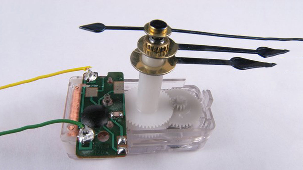
The mechanical aspect is extremely simple. The clock functions similarly to a stepper motor, with the movement of the mechanical part being advanced a specific distance forward by charging an electric coil. In this situation, with each activation, the second hand moves forward one position while making the recognizable ticking noise. To turn on the electric coil, simply supply it with a voltage. The sole difficult aspect is reversing the voltage to advance the clock to the next stage. Accomplishing this requires using two Arduino pins and altering their polarity. (hint: make sure to click on the image to view the annotations). Inside the dismantled clock, I found a compact built-in controller. I used a razor blade to cut the copper wires connecting the connections to the electromagnet, which resulted in the original chip being disconnected, and then I left it.
By supplying voltage to the coil, it initiates the production of current which results in the formation of a magnetic field surrounding the coil. The magnetic field causes a permanent magnet attached to a gear to experience a force, resulting in the magnet rotating and aligning with the electromagnet. This device undergoes a 180-degree rotation which is then transformed into a 6-degree rotation through a set of gears with a 1:30 reduction ratio. In the next stage, we must change the voltage polarity to create a magnetic field pointing in the opposite direction, causing the permanent magnet to rotate again. One can also imagine a setup with a spring and a ratchet to return the permanent magnet to its original position, but that is not how these clocks work.
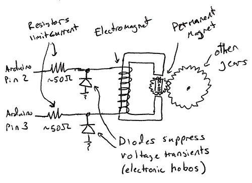
Therefore, with this understanding, we ought to be capable of linking both ends of the electromagnet to the Arduino in order to make it operational. Due to its low power consumption, it can be powered directly from the Arduino ports as it is designed to run on a single battery for several months, if not years. There are just two factors we need to take into account in the circuit. Initially, it is important to insert a resistor in the circuit together with the coil in order to restrict the flow of current. I selected two resistors with a 50 ohm value, and positioned one at either end of the coil. You might have to try different values to determine what is effective. Additionally, it is advised to place diodes from ground to each electromagnet to prevent high voltage spikes when discharging and charging the magnet, as it acts like an inductor. This will prevent the voltage from dropping below the diode’s threshold of approximately .7 volts for the specific diodes selected.
For more detail: Controlling a clock with an Arduino
- Can I drive the clock coil directly from Arduino pins?
Yes; the coil is low power and designed for long battery life, so it can be driven from Arduino pins with proper resistors and diodes. - How do you reverse the coil polarity to advance the clock?
Use two Arduino pins connected to each end of the coil and toggle their polarity to reverse the voltage across the coil. - Do I need resistors in series with the coil?
Yes; add series resistors (the author used two 50 ohm resistors) to limit current through the coil. - Are diodes necessary when switching the coil?
Yes; diodes from ground to each electromagnet end prevent high voltage spikes when discharging the coil. - What happens mechanically when the coil is energized?
The coil creates a magnetic field that rotates a permanent magnet 180 degrees, and the gear reduction converts that to a 6 degree step of the second hand. - Was the original clock controller removed?
Yes; the author cut the copper traces to disconnect the built-in controller before wiring to the Arduino. - Is there any software issue to watch for?
Yes; the Arduino program has a precision issue related to a 9.54 hour rollover event, and Rob Faludi provided a solution referenced by the author.