This might seem totally useless, considering how advance current technology can be and you might even be like “Tsk! a Thermometer?”
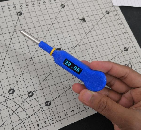
But there is a lot of experiment based on temperature (water temperature, room temperature, etc) so digital thermometer becomes a key instrument for temperature measurement considering the other alternatives and cost/performance ratio. It is used from measuring temperature of human body to measuring temperature of chemical substances. So, In this Instructable we’ll build a digital thermometer which runs on a single CR2032 cell for almost 140days! (In makers term that is amazing!) and also run through optimizing the code and circuit for running in low power. Just to add some nostalgic moment, I used the piezo sensor to reset the thermometer that people usual do with a Mercury-in-glass thermometer.
So, enough with the story grab your supplies and let’s get started.
Supplies
These are the list of products which can help you do this project with ease
(Affiliate Link)
- ATTINY 85 : https://amzn.to/3bB8t8p
- ATTINY dev board : https://amzn.to/3bC1cp3
- Piezo : https://amzn.to/2S6yo0V
- Arduino Nano : https://amzn.to/3tY8I3E
- PETG filament : https://amzn.to/3w6bB46
- DS18B20 : https://amzn.to/3ylGRy0
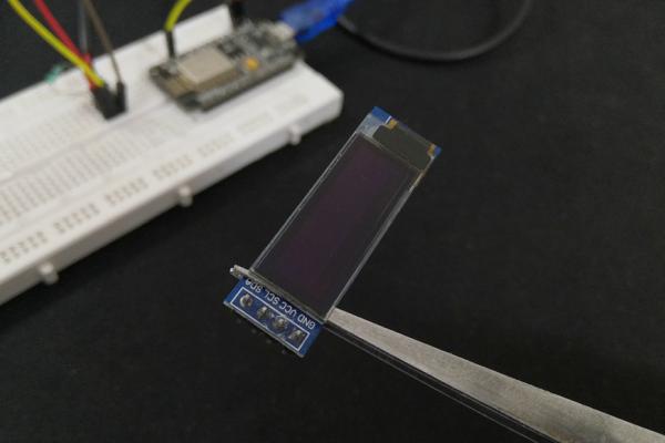
- OLED display : https://amzn.to/2VcEATc
- CR2032 : https://amzn.to/3ysFiOX
- CR2032 battery holder : https://amzn.to/3fsFhl8
- Resistor Kit : https://amzn.to/3frj4nx
- 3d Printer : https://amzn.to/3trVWKw
- Printer Upgrades : https://amzn.to/3hbK3Ga
Step 1: Temperature Sensor DS18B20
Let’s start with the core part of the project, the temperature sensor.
Why DS18B20?
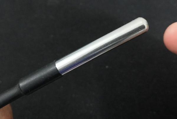
There are different sensors to choose from, based on accuracy, type and how they transfer the data to the microcontroller. but I chose the DS18B20, because it’s very well designed to read temperature from an external object, and it requires only one wire to read the data from this sensor. Also this is better for this project because of the metal probe, or it would be difficult to make a custom metal probe to make the contact point and the other major reasons are, the sensor is supported by a variety of libraries with Arduino and consumes only 5uA when it’s on sleep mode.
Step 2: Interfacing DS18B20 With a Microcontroller
To interface this. You can use any microcontroller because the sensor uses a protocol called one wire which is totally dependent on the software rather than the hardware, all you need is a single GPIO pin of the microcontroller.
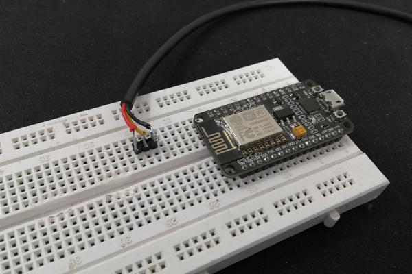
Just for the sake of this example I will use the Nodemcu. The circuit connection is easy as it gets. Connect the power supply i.e red wire to +3.3V, black wire to ground and the yellow data wire to D2 of the NodeMCU, that’s it. finally Don’t forget this important step, add a 4.7k pull resistor between the 3.3v and the data pin. If not, the microcontroller won’t read the data from the sensor.
Step 3: Testing DS18B20
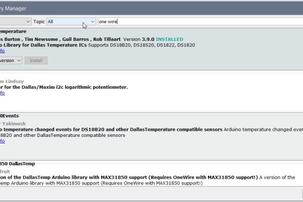
Now we can program the Nodemcu, Just go to your Arduino IDE and download the Dallas temperature sensor library and one wire library. Once that’s been installed. Go to example and open the simple temperature sensor example and change the pin wherever the sensor is connected too, in my case it’s pin D2 which is GPIO 4.
Compile and upload the code.
Once, the code is uploaded you can open the serial monitor. You see the sensor data is shown here, but this DS18B20 sensor doesn’t instantly show accurate temperature readings same as commercial thermometers, it takes a while to settle down at the correct value, you can also see how this affects in the final build. So, for the sake of this experiment, I have reduced it to the measurement time to 15 seconds. But in case you need a better accuracy you can always increase the measurement time in the code.
Step 4: Interfacing 128X32 OLED Display
As we can now read the temperature, let’s try to display this on an OLED display. In most of my previous instructables I have used this, if you like to learn more check out this links:
I used a 0.91 inch OLED display with 4 pins, connect the SCL of the display to D1, and the SDA of the display to D2, because D1 and D2 are the default I2C pins of the NodeMCU and to power the display connect the VCC and ground of the module to 3.3v and ground of the NodeMCU.
Step 5: Testing the OLED
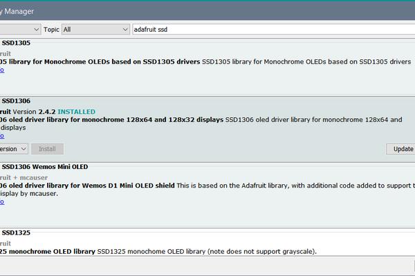
To test if the OLED display is working or not, go to your Arduino IDE and download the Adafruit SSD1306 library from the library manager.
[Go to Sketch -> include library -> Manage Library -> Adafruit SSD1306]Now open the sketch Hardware_test.ino, compile and upload the code to your Nodemcu. Now with that we can read the temperature and show it on the OLED display. Everything working pretty great!
Step 6: Peizo Sensor
But the current setup reads the sensor value continuously. I would rather want this to stop reading the temperature after a while and restart when we give some input. For this you can use a button but in the intro you would have seen the thermometer is triggered by slamming. This was simpler to implement than you expect. I neither used complicated sensors nor complex coding. Instead I used a very simple piezo sensor.
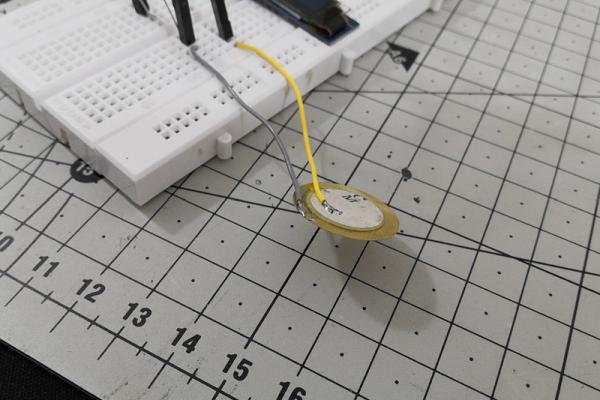
This is quite a little interesting sensor. This contains a small crystal between 2 metallic plates, when pressure is applied to this crystal, the sensor outputs a small electric current. So, we can build a very simple circuit to measure this current and do some task based on the reading.
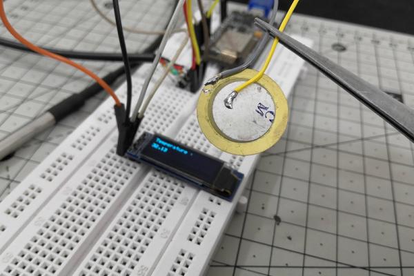
Step 7: Interfacing and Testing Peizo Sensor
Again the circuit is very simple, just build a voltage divider using the 5.6kresistor with the piezo sensor. Then connect the junction to the pin A0 of the NodeMCU. For the code just do an analog read and display it on the serial monitor.
You can see the value changes as we apply varying pressure to the sensor. Now we add this to our existing circuit and add a threshold to the sensor value inside the code, So wherever the piezo hits this value the code will reset and the temperature reading will start again. (Upload the Hardware_test.ino file from previous step)
You can see this works exactly as we expected! But this is not the same logic we will use with sensors in the final build, but a little different, which we’ll discuss more on that later.
Step 8: Finding a Microcontroller Alternative
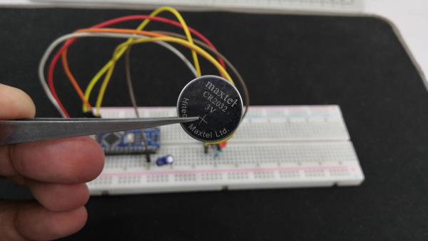
Let’s say we want the whole circuit to work with just this single CR2032 cell. It would be close to impossible because this single cell (3.3V / 210mah) won’t even be powerful enough to run Arduino UNO/Nano nor the NodeMCU(ESP8266) so there is no way it will run the entire circuit with temperature sensor, piezo and the display.
We need an alternative microcontroller which doesn’t need much power as well as can run the display, temperature sensor and the piezo with this single cell. This might be too much to ask, but lucky there is a microcontroller which can do all this! Meet the ATTINY 85.
Step 9: ATTINY 85
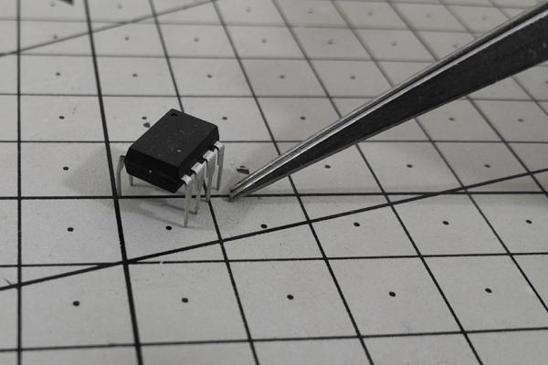
This is an 8 bit microcontroller with 8 pins and has all the features that we exactly need, a I2C to drive the OLED display, an input pin to read the temperature reading and also analog input to read the piezo reading. Mostly importantly this can do all this while being powered by just a single 3.3v cell.
But it comes with it’s own disadvantages. It’s slightly complicated to program, the storage is limited to 8kb and ram is just 512 bytes and also it has just 5 usable pins. We can use the reset pin as GPIO but it just makes things way more complicated than it was initially. So, deciding the microcontroller was purely based on a few simple questions: Is that enough? Can we fit everything in ? Do I have it? Can I program it? In my case, it’s a big YES!
Step 10: Interfacing ATTINY 85
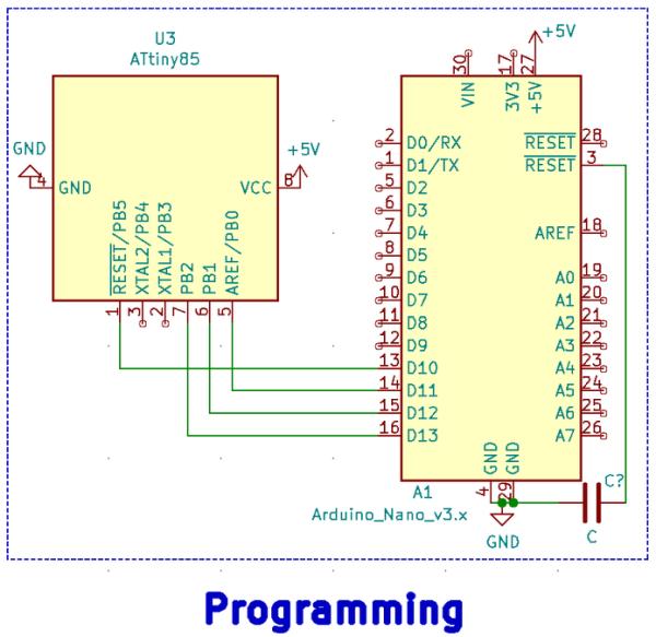
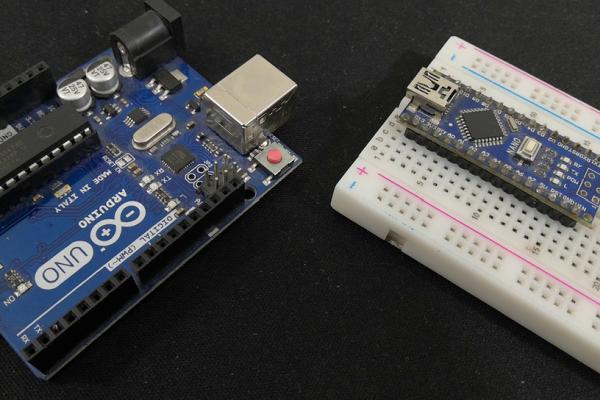
So, let me show you how to program this attiny 85, for this we need an arduino which supports ISP, both arduino nano or uno can be used. I will be using the nano as an example to show how to program this microcontroller.
First step is to prepare the arduino. Just connect the board to your computer and open the arduino IDE. Now, go to examples and open the Arduino ISP example. Just compile and upload this code to your arduino nano. That’s all the setup we need, next start with the connection between the arduino nano and the attiny 85, connect the power VCC to 3.3v and ground to ground. Then connect pin D13 to pin7, pinD12 to pin6, pinD11 to pin5 and finally pinD10 to pin1. And add an electrolytic capacitor between arduino nano reset and ground. If you like to follow along you can check the link in the description for the circuit diagram for the connection.
Step 11: Testing ATTINY 85
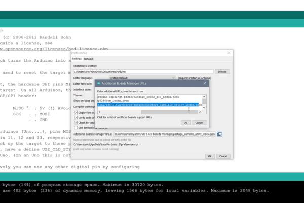
Once the connection is done, open the Arduino IDE, go to preference and paste this link. [https://raw.githubusercontent.com/damellis/attiny/ide-1.6.x-boards-manager/package_damellis_attiny_index.json] This will let the Arduino IDE to download attiny core.
Go to the board manager and search for attiny, and install the board. Now change the board, processor to attiny 85, clock to 8Mhz and finally the port to where Arduino Nano is connected. Once this setup is done go to tools and click on burn bootloader.
This completes the programming setup for the ATTINY 85. We can test this by running a simple blink sketch. Connect a led on pin 3 of the 85 then write and modify the blink sketch to drive that pin in our case I have connected the LED to GPIO D4 which is pin 3.
Then make sure the ATTINTY 85 settings are selected under tools and upload the code.
And there you go, successfully programmed the ATTINY85!
Step 12: Verify Power Consumption of the Circuit
Before diving into using other components with this let’s just verify if the current supplied by this single 3V cell is enough to drive all the components.
So the cell I’m using is CR2032. This cell has a capacity of 210mAh, and a peak current draw of 30 mA. So we have to keep everything under atleast 20mA to work perfectly.
ATTINY 85 needs little less than 4mA [datasheet] running at 3.3V at 8Mhz and the temperature sensor DS18B20 needs 1.5mA [datasheet] while it’s reading the temperature and the oled display needs 20mA [datasheet] when displaying all the pixels on the screen. Combined all this together we are still less than the peak current draw 30mA.
Source: Contact Digital Thermometer With Deep Sleep [Attiny85]