Summary of How to connect a servo to the Arduino
Summary: The article explains wiring continuous-rotation servos for the BOE Shield-Bot. Servo cables have ground (black), power +5V (red), and signal (white/yellow). It shows breadboard hand-wiring using shared ground and +5V while routing signals to separate Arduino pins (left servo to D10, right to D11). It also describes the BOE Shield-Bot servo header that accepts up to four servos (D10–D13) with proper orientation to avoid shorts.
Parts used in the BOE Shield-Bot Servo Connection Project:
- Continuous rotation servo(s)
- 3-wire servo cable (black ground, red power, white/yellow signal)
- Arduino (with digital pins 10, 11, 12, 13)
- Breadboard
- Two 3-pin headers
- Jumper wires (recommended colors: black, blue, yellow, two red)
- BOE Shield-Bot Shield with servo header
Servo Cable
The continuous rotation servos that come with the BOE Shield-Bot have a 3-wire cable for connecting it to the power and controller. The black wire is the ground, the red wire is the power (positive) and the white wire (sometimes yellow, depending on the servo) is the signal wire. The signal wire is used to send the control signal to the servo. All three wires run together into a single, standard hobby servo connector.
Wiring the Connection with a Breadboard
To help you to understand how the servo connections work, we are going to show you how to hand wire the connections.
First we are going to use the two 3-pin headers to connect the servo cables to the breadboard. To do this we are going to need five jumper wires; functionally the wires can be of any color, but to follow the circuit we recommend that you have one black wire, one blue wire, one yellow wire, and two red wires (left).
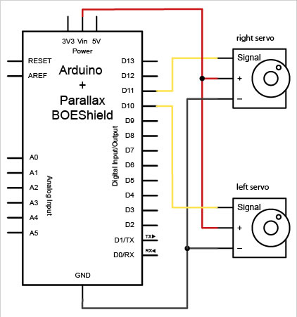
Next we want to look at the schematic for the connections (right).
As you can see, both servos have their black wires connected to ground and their red wires connected to 5V. However, the white signal wires each connect to a different Arduino pin. The left servo gets connected to digital pin 10, while the right servo gets connected to digital pin 11. This is because we want to be able to control the servos independently.
Since the black wires are both being connected to ground (called ‘common ground’), we can connect both of the black wires to one ground port. Likewise, the two red wires can be connected together to the a +5 volt port (since they are both using +5 volts). The two white signal wires, however, will be using two different signal pins in order to control the servos independently and should not be wired together.
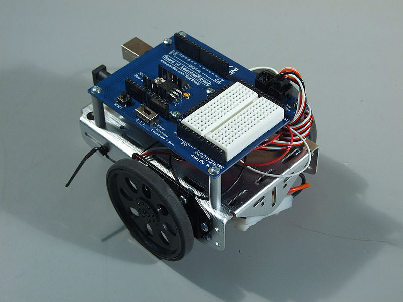
BOE Shield-Bot Shield connections
While hand wiring the connections is not hard, it does take up a large amount of space on the breadboard that could be used for other components. Thankfully, the BOE Shield-Bot Shield has four connections on the shield that allow you to plug the servo connectors directly into the board. On the shield (near the edge of the breadboard) you will see a group of pins shielded by plastic.
These are the servo pins. When connecting the servos, always make sure that they are correctly orientated (as noted on the shield’s silkscreening; the black wire should be closest to the breaboard). Plugging the servos in the wrong way could cause a short and damage the servo (and possible the Arduino). The servo bank is wired to the Arduino’s digital pins 10, 11, 12 and 13. You can tell which pin the signal is connected to by the small number near the signal wire of the plug.
For more detail: How to connect a servo to the Arduino
- What do the three wires on the servo cable do?
The black wire is ground, the red wire is power (+5V), and the white or yellow wire is the signal wire used to send control signals to the servo. - How do you wire two servos on a breadboard?
Connect both black wires to common ground, both red wires to +5V, and connect each white signal wire to a different Arduino digital pin (example: D10 and D11). - Can the two signal wires be connected together?
No. The two signal wires should not be wired together because each servo needs an independent control signal. - Which Arduino pins does the BOE Shield-Bot servo bank use?
The servo bank on the BOE Shield-Bot is wired to Arduino digital pins 10, 11, 12, and 13. - How should servos be oriented when plugged into the BOE Shield-Bot shield?
Orient the servo so the black wire (ground) is closest to the breadboard as indicated on the shield silkscreening. - What can happen if a servo is plugged in the wrong way on the shield?
Plugging a servo in the wrong way can cause a short and may damage the servo and possibly the Arduino. - Why use the BOE Shield-Bot shield instead of hand wiring on a breadboard?
The shield lets you plug servos directly into the board, saving breadboard space for other components.