Summary of Component Designing in Proteus ISIS
This tutorial explains how to design a simple 4‑pin custom component in Proteus ISIS for presentation purposes: create a 2D graphics box, add device pins, set each pin name and number, ensure the wireable end is free, then group the drawing and use Make Device to add it to the Proteus library with a device name and category. The created part can then be searched and placed in designs for presentation (it will not simulate as a real component).
Parts used in the Test Device:
- 2D Graphics Box (Proteus 2D Graphics tool)
- Device Pin (Proteus Device Pins tool) — 4 pins
- Pin properties dialog (for Pin Name and Default Pin Number)
- Selection tool (to select whole component)
- Make Device command (to create library device)
- Device properties dialog (to enter Device Name and Category)
Hello friends, hope you all are having fun in your life. Today’s tutorial is about the component designing in Proteus ISIS. This tutorial actually deals with the presentation of your project. Usually when students give presentation of their projects, then it is asked that add the circuit diagram of their project. Now when students open Proteus in order to design their circuit, they found out that the components they have used in their project are not available in the Proteus Directory. Now what to do ?
  In that case, there’s a need to design your own component in Proteus and place it in the circuit. Although, this new designed component won’t work as the real component but for presenting the circuit, it will be enough. ofr example, we don’t have Arduino boards in Proteus software. so, I have designed some of the Arduino baords myself for Proteus which you can download from Arduino Library for Proteus.

Similarly, it usually happens to me during my freelancing work to design some circuit and when I don’t find the required component in the Proteus library then I simply design it on my own and then create its PCB. We will check the PCB designing of such components in the coming posts of this tutorial. So, now let’s get started with component designing in Proteus ISIS.
Component Designing in Proteus ISIS
- Now I am going to design a simple component having 4 pins.
- First of all select the 2D Graphics Box Mode as shown in the below figure.
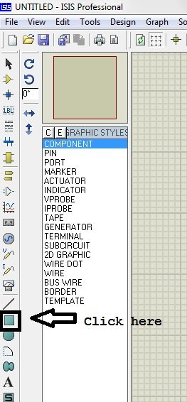
- Now click on the workspace and drag the cursor to create a box, as shown in the below figure.
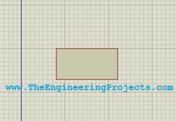
- We have created the body of our component, now there’s a need to add pins in it.
- For this, click on the Device Pins Mode as shown in the below figure and click on the workspace.
- It will add a small pin, attach this pin with the box as I did in the below figure.

Note:
- The pin has a small green bubble on it. Make sure that this end is not connected with the box as this bubble end is for the wire.
- I have added four pins with the box. Now there’s a need to name these pins. For this purpose, double click any of the attached pin and the properties box will open up as shown in the below figure.
- Mention the Pin Name and the Default Pin Number, it will appear on the component and then click on Next.
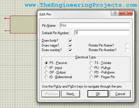
- When you click Next, it will ask for the same things for the second pin and so on.
- When you fill these info for all the four pins then click OK.
- Now when you click the ok button, your component will now look as shown in the below figure.
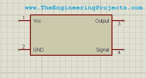
- I have given my pins the names as Vcc, GND, Output, Signal.
- We have completed all the info of our product, now there’s a need to add this component in our library.
- For this purpose, select the whole component and then right click and select Make Device.
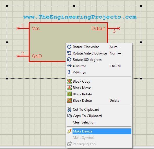
- When you click on this option a new dialog box will open up as shown in below figure.
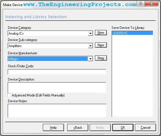
- In this dialog box, you just need to give info of your new component so that you can search it easily in your Proteus library.
- Just fill the Device Name in it and click Next. I have given the name Test Device to my component.

- Now click Next and go on clicking Next, unless you reach at the below page.
- Here you need to place your component in the category. Choose the appropriate category for your product and click on OK.
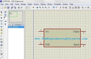
That’s it. Now your component has been added to the library. Open your part list and search for the component like in my case I search for Test Device and the below component appeared in my list.
That’s all for today. If you have any questions regarding this tutorial, ask in comments and I will reply them. Take care.
- How do I start designing a component in Proteus ISIS?
Begin by selecting the 2D Graphics Box Mode and drawing the component body on the workspace. - How do I add pins to my custom component?
Use the Device Pins Mode, click to add pins, and attach each pin to the box while keeping the wireable bubble end free. - How do I name and number the pins?
Double click a pin to open the properties box, enter the Pin Name and Default Pin Number, then click Next for subsequent pins. - What precaution is mentioned about the pin bubble?
Ensure the small green bubble end of the pin is not connected to the box because that end is for the wire. - How do I convert my drawn item into a library part?
Select the whole component, right click, and choose Make Device to create a library device. - What information is required when making the device?
Provide a Device Name and then proceed through the dialog to assign an appropriate category before clicking OK. - Can the custom component simulate like a real component?
No, the tutorial notes that the designed component will not work as the real component but is sufficient for presentation. - How do I find my newly added component in Proteus?
Open the part list and search by the Device Name you entered (for example Test Device) to locate it.