
Summary of Auto Intensity Control of Power LED using Arduino
This article describes an Arduino-based automatic LED dimmer that adjusts a 1W Power LED's brightness based on ambient light levels using an LDR and PWM. Unlike simple on/off circuits, this system varies intensity proportionally to darkness, turning the light off completely when it is bright outside.
Parts used in the Automatic LED Dimmer:
- Arduino UNO
- LDR
- Resistor (510 ohm)
- Resistor (100k ohm)
- Capacitor (0.1uF)
- Transistor 2N2222
- 1 watt Power LED
- Connecting wires
- Breadboard
Be a bright spark, lights off till it’s dark!” sometimes we forget to turn off the lights and waste electricity and you must have also seen street light turned on in the day. We have already built few circuits on Dark detector where lights turn off automatically if it is bright outside and turns ON if it is dark outside. But this time, in this circuit we are not only turning On and off lights based on light conditions but also varying the intensity of light according to outside light conditions. Here we have used LDR and PWM concept with Arduino for decreasing or increasing the brightness of the 1 watt Power LED automatically.
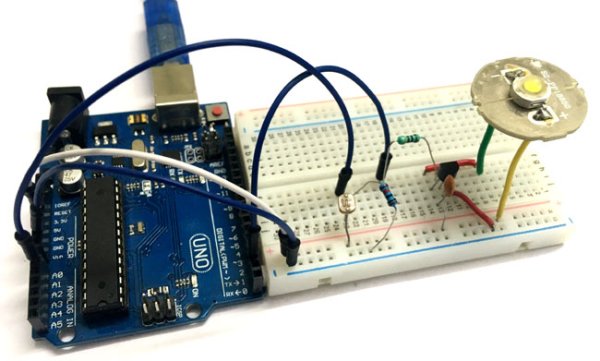
Basically, PWM refers to Pulse Width Modulation, the output signal via a PWM pin will be an analog signal and acquired as a digital signal from the Arduino. It uses the duty cycle of the digital wave to generate the sequential analog value for the signal. And, that signal is further used to control the brightness of the Power LED.
Material Required
- Arduino UNO
- LDR
- Resistor (510, 100k ohm)
- Capacitor (0.1uF)
- Transistor 2N2222
- 1 watt Power LED
- Connecting wires
- Breadboard
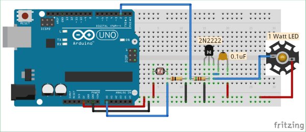
Circuit Diagram
Code and Explanation
The complete Arduino code for Automatic LED dimmer is given at the end.
In the below code, we are defining the PWM pin and the variables to be used in the code.
int pwmPin = 2; // assigns pin 12 to variable pwm
int LDR = A0; // assigns analog input A0 to variable pot
int c1 = 0;   // declares variable c1
int c2 = 0;   // declares variable c2
Now, in the loop, we are first reading the value using the command “analogRead(LDR)” then save the analog input into a variable named “value”. By doing some mathematic calculation we are generating the PWM signal. Here, we are controlling the intensity of light using PWM only if the analog value is less than 500, and if it is more than 500 we completely turn off the lights.
  int value = analogRead(LDR);
  Serial.println(value);
  c1= value;
  c2= 500-c1;     // subtracts c2 from 1000 ans saves the result in c1

  if (value < 500)
  {
  digitalWrite(pwmPin, HIGH);
  delayMicroseconds(c2);
  digitalWrite(pwmPin, LOW);
  delayMicroseconds(c1);
  }

  if (value > 500)
  {
    digitalWrite(2,LOW);
  }
}
You can learn more about PWM in Arduino from here.
How it Controls the Light Intensity Automatically:
As per the circuit diagram, we have made a voltage divider circuit using LDR and 100k resistor. The voltage divider output is feed to the analog pin of the Arduino. The analog Pin senses the voltage and gives some analog value to Arduino. The analog value changes according to the resistance of LDR. So, if is dark over the LDR, its resistance get increased and hence the voltage value (analog value) decreases. Hence, the analog value vary the PWM output or the duty cycle, and duty cycle is further proportional to intensity of light of power LED. So the light over the LDR will automatically control the intensity of Power LED. Below is the flow diagram how this will work, upside arrow sign is indicating “increasing” and downside arrow sign is indicating “decreasing”.
Intensity of light (on LDR) ↓ – Resistance↑ – Voltage at analog pin↓ – Duty cycle (PWM)↑ –Brightness of Power LED ↑
If its full bright outside (when analog value increases more than 500) the power LED turns off.
This is how you can control the intensity of light automatically using LDR.
Further check our all the LDR related circuits here.
Read more: Auto Intensity Control of Power LED using Arduino
- How does the circuit control light intensity automatically?
The circuit uses an LDR and voltage divider to sense ambient light; as darkness increases, resistance rises, changing the analog value which adjusts the PWM duty cycle to increase LED brightness. - What happens if the analog value is more than 500?
If the analog value exceeds 500, indicating full brightness outside, the power LED turns off completely. - Which concept is used with Arduino to vary light intensity?
Pulse Width Modulation (PWM) is used to generate sequential analog values that control the brightness of the Power LED. - Can this circuit turn lights on only when it is dark?
Yes, the circuit turns the light on and varies its intensity when it is dark, while keeping it off during the day. - What type of LED is used in this project?
A 1 watt Power LED is used in this circuit. - Does the resistance of the LDR change with light conditions?
Yes, if it is dark over the LDR, its resistance increases, causing the voltage value at the analog pin to decrease. - How is the PWM signal generated in the code?
The code reads the analog input from the LDR and calculates a duty cycle using delayMicroseconds to control the digital output pin. - What component is used to create a voltage divider circuit?
An LDR and a 100k resistor are used to make the voltage divider circuit.
