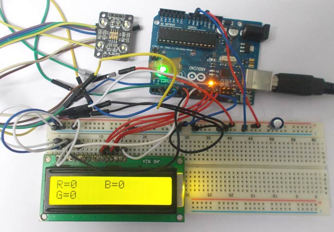
Summary of Color Detector using Arduino Uno
This project interfaces a TCS3200 color sensor with an Arduino UNO to detect colors using RGB photodiode arrays and selectable optical filters. The module outputs frequency proportional to selected color intensity; selection is done via S2 and S3 pins. A 16x2 LCD displays readings. The guide includes required components, LCD and sensor wiring, and explains using two LCD control pins (RS, E) while grounding contrast and RW for simplicity. Setting S2 and S3 LOW selects red detection; other combinations select green, blue, or no-filter white mode.
Parts used in the TCS3200 Color Sensor with Arduino UNO Project:
- Arduino UNO
- Power supply (5V)
- LED
- JHD_162ALCD (16x2 LCD)
- TCS3200 color sensor module
- Connecting wires/jumper cables
- Breadboard or PCB for wiring
In this project we are going to interface TCS3200 color sensor with Arduino UNO. TCS3200 is a color sensor which can detect any number of colors with right programming. TCS3200 contains RGB (Red Green Blue) arrays. As shown in figure on microscopic level one can see the square boxes inside the eye on sensor. These square boxes are arrays of RGB matrix. Each of these boxes contain Three sensors, One is for sensing RED light intensity, One is for sensing GREEN light intensity and the last in for sensing BLUE light intensity.
Each of sensor arrays in these three arrays are selected separately depending on requirement. Hence it is known as programmable sensor. The module can be featured to sense the particular color and to leave the others. It contains filters for that selection purpose. There is forth mode that is no filter mode. With no filter mode the sensor detects white light.
Components Required
Hardware: ARDUINO UNO, power supply (5v), LED, JHD_162ALCD (16*2LCD),TCS3200 color sensor.
Software: ARDUINO IDE (ARDUINO nightly).
Circuit Diagram and Working Explanation
In 16×2 LCD there are 16 pins over all if there is a back light, if there is no back light there will be 14 pins. One can power or leave the back light pins. Now in the 14 pins there are 8 data pins (7-14 or D0-D7), 2 power supply pins (1&2 or VSS&VDD or GND&+5v), 3rd pin for contrast control (VEE-controls how thick the characters should be shown), and 3 control pins (RS&RW&E)
In the circuit, you can observe I have only took two control pins. The contrast bit and READ/WRITE are not often used so they can be shorted to ground. This puts LCD in highest contrast and read mode. We just need to control ENABLE and RS pins to send characters and data accordingly. [Also check: LCD interfacing with Arduino Uno]
The connections which are done for LCD are given below:
PIN1 or VSS to ground
PIN2 or VDD or VCC to +5v power
PIN3 or VEE to ground (gives maximum contrast best for a beginner)
PIN4 or RS (Register Selection) to PIN8 of ARDUINO UNO
PIN5 or RW (Read/Write) to ground (puts LCD in read mode eases the communication for user)
PIN6 or E (Enable) toPIN9 of ARDUINO UNO
PIN11 or D4 to PIN7 of ARDUINO UNO
PIN12 or D5 to PIN11 of ARDUINO UNO
PIN13 or D6 to PIN12 of ARDUINO UNO
PIN14 or D7 to PIN13 of ARDUINO UNO
The connections which are done for color sensor are given below:
VDD to +5V
GND to GROUND
OE (output Enable) to GND
S0 to UNO pin 2
S1 to UNO pin 3
S2 to UNO pin 4
S3 to UNO pin 5
OUT to UNO pin 10
The color which needs to be sensed by the color sensor is selected by two pins S2 and S3. With these two pins logic control we can tell sensor which color light intensity is to be measured.
Say we need to sense the RED color intensity we need to set both pins to LOW. Once that is done the sensor detects the intensity and sends the value to the control system inside the module.
Read More: Color Detector using Arduino Uno
- What does the TCS3200 color sensor contain?
The TCS3200 contains RGB arrays of photodiodes with filters and a no-filter mode to detect white light. - How do you connect the TCS3200 power pins?
Connect VDD to +5V and GND to GROUND. - How is the color selected on the TCS3200?
Color is selected by setting logic on pins S2 and S3. - Which Arduino pin reads the sensor output?
The sensor OUT pin is connected to UNO pin 10. - How do you select red color detection?
Set both S2 and S3 pins to LOW to sense red intensity. - Which LCD pins are used for control in this setup?
Only RS and E are used; RW and VEE (contrast) are grounded. - How are LCD data pins connected to the Arduino?
LCD D4 to UNO pin 7, D5 to UNO pin 11, D6 to UNO pin 12, D7 to UNO pin 13. - Why is RW grounded on the LCD?
Grounding RW puts the LCD in read mode and simplifies communication by avoiding the read/write control. - What happens in no-filter mode on the sensor?
In no-filter mode the sensor detects white light.