
Summary of Automatic Room Light Controller with Bidirectional Visitor Counter
This article details an Arduino-based automatic room light controller featuring a bidirectional visitor counter. The system uses two IR sensors to detect entry and exit, incrementing or decrementing a count displayed on an LCD. When the count reaches zero, a relay turns off the lights; otherwise, they remain on. This project serves as an educational tool for hobbyists to learn about microcontroller interfacing, sensor logic, and automated lighting control.
Parts used in the Automatic Room Light Controller with Bidirectional Visitor Counter:
- Arduino UNO
- Relay (5v)
- Resisters
- IR Sensor module
- 16x2 LCD display
- Bread Board
- Connecting Wires
- Led
- BC547 Transistor
Often we see visitor counters at stadium, mall, offices, class rooms etc. How they count the people and turn ON or OFF the light when nobody is inside? Today we are here with automatic room light controller project with bidirectional visitor counter by using Arduino Uno. It is very interesting project for hobbyists and students for fun as well as learning.
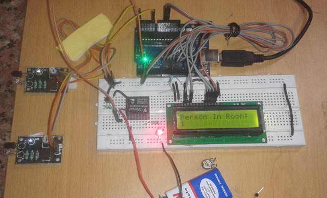
Components
- Arduino UNO
- Relay (5v)
- Resisters
- IR Sensor module
- 16×2 LCD display
- Bread Board
- Connecting Wires
- Led
- BC547 Transistor
The project of “Digital visitor counter” is based on the interfacing of some components such as sensors, motors etc. with arduino microcontroller. This counter can count people in both directions. This circuit can be used to count the number of persons entering a hall/mall/home/office in the entrance gate and it can count the number of persons leaving the hall by decrementing the count at same gate or exit gate and it depends upon sensor placement in mall/hall. It can also be used at gates of parking areas and other public places.
This project is divided in four parts: sensors, controller, counter display and gate. The sensor would observe an interruption and provide an input to the controller which would run the counter increment or decrement depending on entering or exiting of the person. And counting is displayed on a 16×2 LCD through the controller.
When any one enters in the room, IR sensor will get interrupted by the object then other sensor will not work because we have added a delay for a while.
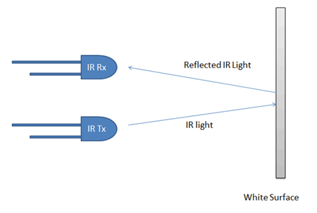
Circuit Explanation
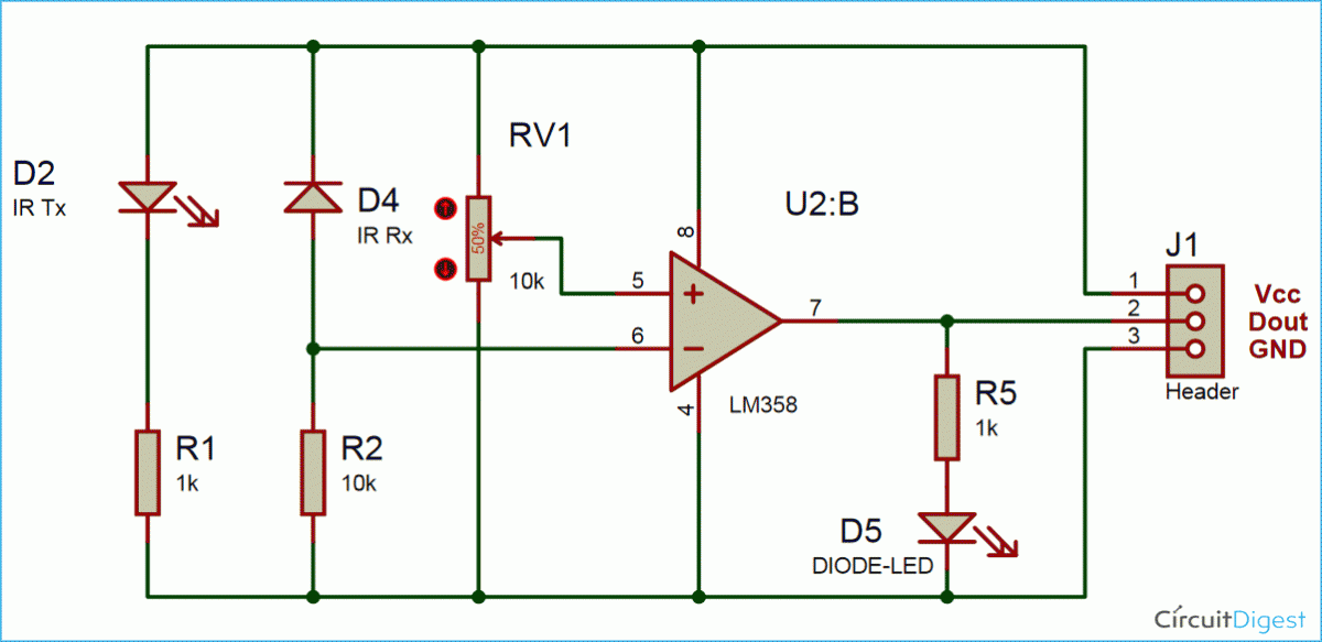
There are some sections of whole visitor counter circuit that are sensor section, control section, display section and driver section.
Sensor section: In this section we have used two IR sensor modules which contain IR diodes, potentiometer, Comparator (Op-Amp) and LED’s. Potentiometer is used for setting reference voltage at comparator’s one terminal and IR sensors sense the object or person and provide a change in voltage at comparator’s second terminal. Then comparator compares both voltages and generates a digital signal at output. Here in this circuit we have used two comparators for two sensors. LM358 is used as comparator. LM358 has inbuilt two low noise Op-amp.
Control Section: Arduino UNO is used for controlling whole the process of this visitor counter project. The outputs of comparators are connected to digital pin number 14 and 19 of arduino. Arduino read these signals and send commands to relay driver circuit to drive the relay for light bulb controlling.
Display section: Display section contains a 16×2 LCD. This section will display the counted number of people and light status when no one will in the room.
Relay Driver section: Relay driver section consist a BC547 transistor and a 5 volt relay for controlling the light bulb. Transistor is used to drive the relay because arduino does not supply enough voltage and current to drive relay. So we added a relay driver circuit to get enough voltage and current for relay. Arduino sends commands to this relay driver transistor and then light bulb will turn on/off accordingly.
Visitor Counter Circuit Diagram
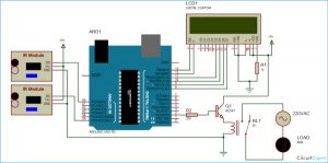
The outputs of IR Sensor Modules are directly connected to arduino digital pin number 14(A0) and 19(A5). And Relay driver transistor at digital pin 2. LCD is connected in 4 bit mode. RS and EN pin of LCD is directly connected at 13 and 12. Data pin of LCD D4-D7 is also directly connected to arduino at D11-D8 respectively. Rest of connections are shown in the below circuit diagram.
Code Explanation
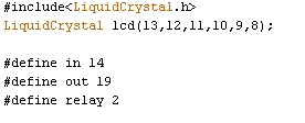
First we have included library for LCD and defined pin for the same. And also defined input output pin for sensors and ralay.
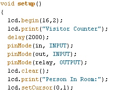
Then given direction to input output pin and initialized LCD in setup loop.
n loop function we read sensors input and increment or decrement the counting depending upon enter or exit operation. And also check for zero condition. Zero condition means no one in the room. If zero condition is true then arduino turn off the bulb by deactivating the relay through transistor.
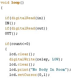
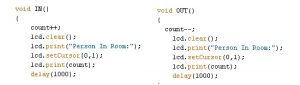
And if zero condition is false then arduino turns on the light. Here is two functions for enter and exit.
Code
#include<LiquidCrystal.h>
LiquidCrystal lcd(13,12,11,10,9,8);
#define in 14
#define out 19
#define relay 2
int count=0;
void IN()
{
count++;
lcd.clear();
lcd.print(“Person In Room:”);
lcd.setCursor(0,1);
lcd.print(count);
delay(1000);
}
void OUT()
{
count–;
lcd.clear();
lcd.print(“Person In Room:”);
lcd.setCursor(0,1);
lcd.print(count);
delay(1000);
}
void setup()
{
lcd.begin(16,2);
lcd.print(“Visitor Counter”);
delay(2000);
pinMode(in, INPUT);
pinMode(out, INPUT);
pinMode(relay, OUTPUT);
lcd.clear();
lcd.print(“Person In Room:”);
lcd.setCursor(0,1);
lcd.print(count);
}
void loop()
{
if(digitalRead(in))
IN();
if(digitalRead(out))
OUT();
if(count<=0)
{
lcd.clear();
digitalWrite(relay, LOW);
lcd.clear();
lcd.print(“Nobody In Room”);
lcd.setCursor(0,1);
lcd.print(“Light Is Off”);
delay(200);
}
else
digitalWrite(relay, HIGH);
}
Video
Read More: Automatic Room Light Controller with Bidirectional Visitor Counter
-
How does the system count people entering and exiting?
The system uses two IR sensors where one detects entry to increment the count and the other detects exit to decrement it. -
Can this project be used in malls or offices?
Yes, the circuit can be used at entrance gates of halls, malls, homes, offices, and parking areas to count persons. -
What component is used as a comparator in the sensor section?
LM358 is used as a comparator because it has built-in low noise Op-amps. -
Why is a transistor added to the circuit?
A BC547 transistor is used to drive the relay because the Arduino does not supply enough voltage and current directly. -
Does the light turn on when no one is in the room?
No, if the count is zero or less, the Arduino deactivates the relay to turn the bulb off. -
Which pins are connected to the IR sensor outputs?
The outputs of the IR Sensor Modules are connected to digital pin number 14 (A0) and 19 (A5). -
How is the LCD connected to the Arduino?
The LCD is connected in 4-bit mode with RS and EN pins at 13 and 12, and data pins D4-D7 at D11-D8. -
What happens after a person enters the room according to the code?
The IN function increments the count, clears the LCD, prints the message, displays the new count, and waits for 1000 milliseconds.
