This project was completed by Alexandra Pittiglio, Christelle El Feghali and Christian Steixner for our Computational Design and Digital Fabrication ‘Material Manipulation Machine’ Project, Semester 2, ITECH M.Sc Programme
Step 1: Concept
How can the material and machine be one entity
We wanted to explore how a material-machine can be informed by its shape change.
Design mechanisms that yield high movement with little actuation.
Dig deep into Material intelligence.
And finally, develop a Clime-Material-Machine feedback loop.
Step 2: The Two Demonstrators

Two demonstrators will be explained in parallel. When neither is referred to specifically it means that the instruction or comment applies to both prototypes.
The manta, materialized as fabric and veneer, Utilizes tensile membrane and embedded
elastic material behavior.
The Birds, materialized as paper, Maximize applied force allowing for minimal movement with maximum shape change.
Step 3: Supplies & Materials
Electronics
– Arduino Uno
– Mosfets IRF 530N
– Flex Sensor
– 10K Resistor for flex sensor
– DHT11 Humidity Sensor
– Jumper Wires
– Breadboard
– Flexinol LT muscle wires (Diameter 150 μm) refered to as “flexinol”
– External 5V power source with high amperes
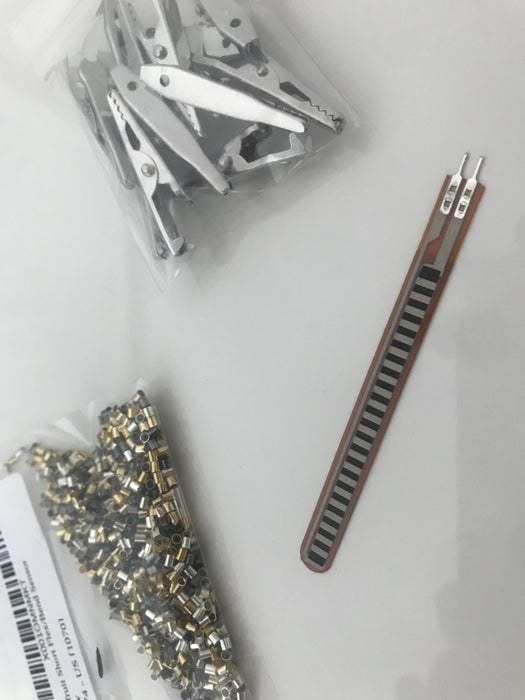
Hardware
Alligator Clips
Crimp Beads
Material (Manta)
Elastic Fabric
Veneer Wood Strips
Material (Birds)
Construction paper
Foam-core Base
Tools
Soldering Iron w/ safety goggles and proper ventilation
Hammer or plyers for crimping
Multi-Meter for flexinol measuring
Xacto knife for cutting
Straight edge ruler
Step 4: Coding
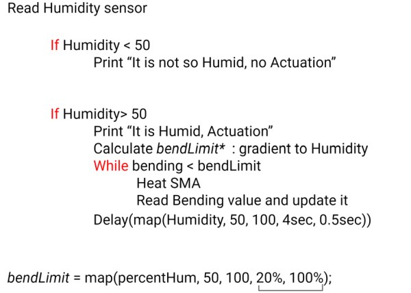
Pseudo Code:
When the humidity is over “A specific interval” actuate bending
Bending will occur until “A specific bending limit” is met
After bending limit is met, a delay time will occur between pulses
In addition to this logic, both the bending limit and the delay intervals change with the humidity increase
As the humidity increases so does the bending limit
As the humidity increases the delay between pulses inversely decreases
Code within IDE:
int flexPin = A0; // pin A0 to read analog input
int sensor = A1; // pin A1 to read analog input
int flexValue; //flex value
int percentFlex; // variable that gives the reading mapped as %
int percentHum;
int percentStop;
const int SMA = 9;
const int ledPin = 3;
void setup() {
// put your setup code here, to run once:
pinMode(ledPin, OUTPUT); //LED out
pinMode(SMA, OUTPUT); //SMA out
Serial.begin(9600); //Begin serial communication
Serial.println(“Environmental test beginning!”); // Just a test
delay(5000);
} // Initiate reading
void loop() {
//Humidity Part
float h = analogRead(sensor); //Assign variable to humidity
percentHum = map(h, 0, 1050, 0, 100);
Serial.println(“Humidity Value % = “);
Serial.println(percentHum); //Now we print log
if (isnan(percentHum)) {
Serial.println(“Failed to read from sensor!”); //If something goes wrong
return;
}
delay(5000);
if (percentHum < 30) {
Serial.println(“It is not so humid, no actuation will occur”);
digitalWrite(ledPin, LOW);
digitalWrite(SMA, LOW);
delay(5000);
}
if ((percentHum >= 30) && (percentHum <= 100)) {
int i = 0;
Serial.println(“It is humid, actuation will begin!”);
percentStop = map(percentHum, 30, 100, 70, 90);
while ((percentFlex < percentStop) && (i <= 10)) {
i = i+1;
digitalWrite(ledPin, HIGH); //turn the LED ON
digitalWrite(SMA, HIGH);
delay(5000);
flexValue = analogRead(flexPin); //Read and save analog value from potentiometer
percentFlex = map(flexValue, 1020, 20, 0, 100); //first value is max reading, second is min reading
Serial.println(“Actuated flex value % = “);
Serial.println(percentFlex); //Print value
digitalWrite(ledPin, LOW); //turn the LED OFF
digitalWrite(SMA, LOW);
delay(map(percentHum, 30, 100, 4000, 10000));
}
}
}
Additional Notes
You may need to download special libraries for humidity sensors within the Arduino IDE
Step 5: Circuit Diagram
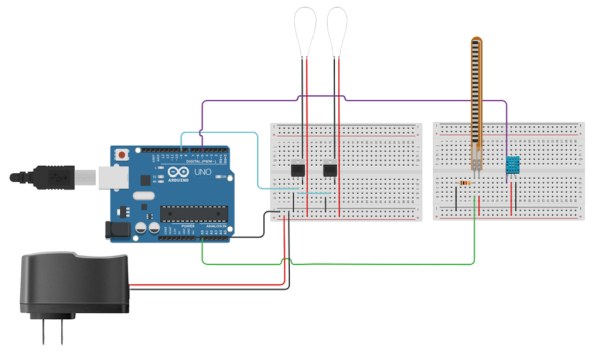
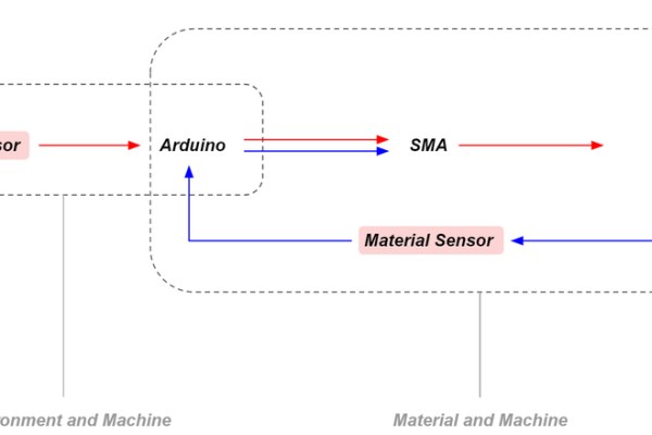
Schematic Overview:
Pin A0 reads flex sensor values
Digital pin 5 reads a humidity sensor
Digital pin 9 is the output for flexinol wires used for actuation
Mosfet where used with the flexinol wires
An external power source with enough amperes is required to actuate the flexinol wires
Note that using a battery source will drain power very quickly
Step 6: Fabrication (Material Assembly)
The material considered for these prototypes where designed to work with the actuation limitations.
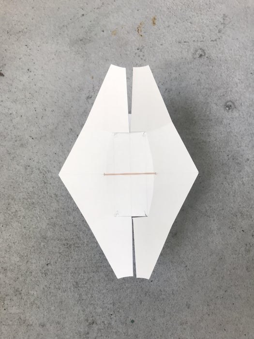
For the Birds, a thick cardstock paper was used because of its light weight and semi rigid properties. The diamond form was chosen for its geometric arrangement that could result in larger triangulated and hexagonal network patterns. The individual panel however had semi circular score lines at folds. These curved etchings is what allows for such great movement as a result of such subtle bending. Since the flexinol does not change shape so greatly this technique was used to amplify movement.
For the Manta, elastic fabric was stretched over a wooden veneer frame until taut. The veneer frame was semi flexible. The elastic fabric forces the veneer to be bent into an anticlastic form as the fabric attempted to relax itself. When the frames opposite adjacent corners were pushed together a “snap” effect occurred where the anticlastic form would reverse itself into a new opposite anticlastic shape. This back and forth snapping was the premise afforded to us by the two materials relationship with one another to which we would later use the flexinol wire to cycle through.
Step 7: Fabrication (Wiring Assembly)
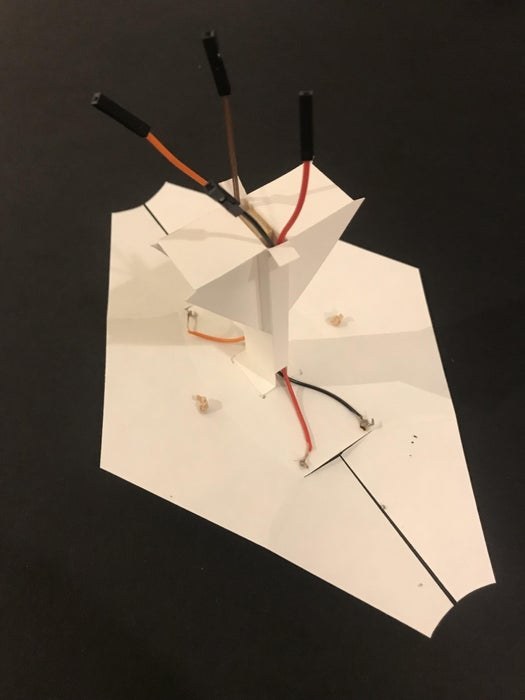
For the bird, the flex sensor is mounted on the portion of the paper panel where the bending magnitude can be measured. Two flexinol wires are run side by side and pinched in the middle to form an “X”. The reason for this was to maximize the deformation change across the wire which is only 3 -5% per the specifications.
Wiring connected to the integrated flex sensor and flexinol can easily get in the way of the actuating material. It is important to consider how these wires will be designed as to not impede or obstruct movement. In the design of the birds, the panel supports are hollowed out and act as chases to run the wiring to and from the breadboard.
When using flexinol it is important to consider that the wires will not only be moving the material but additionally any wiring, intermediate connection pieces, and sensors. In the birds prototype, the mounted flex sensor that runs on top of the material is an additional component that the wire must bend, based on the individual project these factors must be considered early in the design as to select and specify the correct pull force.
Jewelry metal beads were used at the ends of the flexinol segments. This is because the thin wire is difficult to connect to the circuit alone. The flexinol wires are made into a “U” shape and fed through the bead. Once the “U” is fished through, the bead is then hammered flat to pinch the wire into place. In some events the pinch was not sufficient and additional knotting was required. During prototyping it is recommended to use alligator clips to connect the flexinol to the circuit for ease of use. During the final prototype creation, the beads were soldered to copper wires and the bulky alligator clips were no longer used. Note, that during soldering the beads the flexinol will contract and change shape, during this process the wire may slip out of the crimped bead.
Source: Climate | Material | Machine