SEE STEP 11 for uploadable code for this cube.
This instructable has mutated over the past few months, and you’ll see a bunch of end results before we get into how to make the cube, and the improvements that have been made over the original construction techniques and original circuit, as well as improvements made on the PC Boards over time.
A couple quick videos of my cube in action are above.
The second video is the cube as a standalone device, and the third video is under PC control via the TTL Serial port.
The serial port is key to allowing it to be controlled by things like a PIC, another Arduino or PCDuino or PC computer which I eventually intend to include the Commodore VIC-20 (that’s the one before the C-64 for those that at least remember the C-64. If you’re asking “why the VIC-20 ?” it’s simple – I still have one!).
Above is the 3.4A board with the ATmega328P installed and the ATmega32A removed.
In this way, you can program the cube using your Arduino.
This video was made when my cube still had the cardboard base rather than the new Cube Base PC Board.
Below you’ll notice the cube doesn’t sync up with the music right away.
That’s because the threshold value had been adjusted for the louder part of the song
and the intro is a much lower amplitude initially.
This “proof of concept” initially done on the Black Edition Classic board led to the 3.5A and eventually the 3.7A boards
I want to acknowledge that many here that contributed ideas and support should all be recognized.
I actually didn’t expect the number of orders for PCBoards although I knew there was a need.
I myself was so taken with the project, that if I had not the knowledge to design a pcb, or wire up the circuit,
I would have bought a board had it been offered. Unfortunately, one was not in the initial instructable when I saw it.
PLEASE DON’T ASK FOR EAGLE FILES for the PCBoards. All my boards are too large to be done in the freeware version of Eagle. I tried Eagle, and basically didn’t like it at all anyway. Thus, there simply aren’t any Eagle files to begin with. I just found it too awkward to use and way too limiting.
Now…on to the instructable.
I was immediately enthralled with the LED Cube instructable by CHR .
I am going to give a piece of advice I saw there that made a lot of sense. READ EVERYTHING including all the comments.
Often there is information and answers to others questions that may answer the questions you might have.
I thought “I COULD MAKE THAT” – but I took it a step further, and decided that I would try to make it so that almost anybody could make it. That is the reason I eventually created the PCBoards to control the cube, and eventually even a Cube Base Board which all but eliminates the wiring from the project. I have also supplied demo code, and one-click-uploader software to get the code onto the board quickly and easily for those that aren’t comfortable with dos-prompt based utilities like AVRDude.
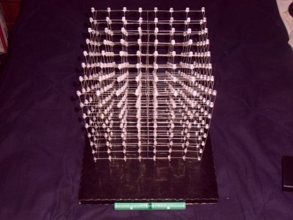
The hardest part is building a cube that is straight and square. I will be addressing this first. The end result is in the photos here.
I have a good electronics background, so I immediately wanted to build one of these.
The more I got into it and read the comments on his well documented instructable, the more I thought I might be able to help people with less of an electronics background understand exactly how this thing actually works.
Not only that, I have made a few improvements along the way as well, plus PC Boards for those that don’t have the skill to build their own the way CHR describes in his instructable.
As I start out, I realize I will be “winging it” a lot here, so forgive me if I am unclear at any point, and feel free to ask questions.
If you see ANODE written where you know it should be CATHODE – or vice-versa – let me know. Sometimes I get tired when writing and get electronic dyslexia, and mix them up. I have tried my best to proof read my instructions to make sure this hasn’t happened.
Try to keep in mind during construction that there is one cathode connection per layer, and 64 anode connections.
I will ask however that if you are getting ready to build one of these, that you go through CHRs well documented instructable FIRST, and then read through this one.
If you are able to, try to build his controller circuit if you can.
THIS can be a VERY daunting task. Many people find they can build the physical cube, and are able to solder connections easily enough, but when it comes to constructing an actual working circuit, that’s where it all falls apart.
FEAR NOT ! As this instructable progresses, I will be working on a number of circuit boards that will include features requested or recommended by people here, and at varying levels of soldering expertise all the way from simple through hole soldering to completely surface mount technology boards.
You will be able to purchase these boards for as close to cost and shipping as possible.
This means prices may drop as more requests for boards come in due to volume discounts.
Watch for board revisions if you have made a recommendation for a board feature that I liked –
such as Stand-Alone Music Input! The video below demonstrates this addition to the 3.7A board,
and the schematic is on step 17 for the passive music trigger circuit.
SIDE NOTE: Yes, this can be powered for an extremely long time off of my other project, the Simplest iPhone Charger.
By the way – come back here every few days to check up on this instructable. I tend to add to it without notice!
This includes additions and revisions to the code.
TO THE PEOPLE THAT WISH TO PURCHASE THE NEW-YEARS January SPECIAL BLACK EDITION BOARD COMBO SET –
The base boards are about 2 weeks out.
Provide your email address with your order, and I will send the parts list and documents for your board ahead of time so you can start ordering your parts now rather than waiting for the Bonus Mini-CD with the parts list on it to arrive with your boards.
All Controller Boards are in stock. You can still order a combo, but you will have to wait at least 2 weeks before the current shipment of V2.0 Black Edition Base Boards arrive.
Send me a private message for details and if you wish to purchase one or more boards.
And now for a SNEAK PEEK at upcoming music triggered modes… (I’ll be working on more as suggestions come in)
Sorry about the video quality on this one, but I was in a hurry to get these posted and didn’t take the time to adjust the camera well.
Just hit the MUSIC button on the 3.5A or 3.7A board to cycle through the music modes.
THIS CODE IS NOW AVAILABLE ON STEP 11 so you guys with the new boards can play! I will be adding to it though!
Step 1: There’s got to be a better way…OR “Building the perfect cube”.
I hated how hard it was always to align the LEDs when soldering them together though, and thought “THERE’S GOT TO BE A BETTER WAY” … but HOW?
I thought “If the LED leads were on the edge of the LED, it would be a snap to line them up.
So it hit me…MOVE the anode to the outside of the LED. If the anode coming from the LED above was on the outside edge, the LED below could sit directly under the LED above it. And if the legs were on the outer perimeter, they would line up easily to be soldered. Not only that, it takes care of measuring because if you solder the leads at the point where they meet, it would always be the exact same distance every time!
So I started bending the leads in this manner, but I was soon suffering from finger fatigue, and it was hard to make the bends precise. Once again, I was thinking there had to be a better way. I tried to think of how a machine programmed to do this automatically would work, and how I could emulate that machine manually. After much thought, I had an idea.
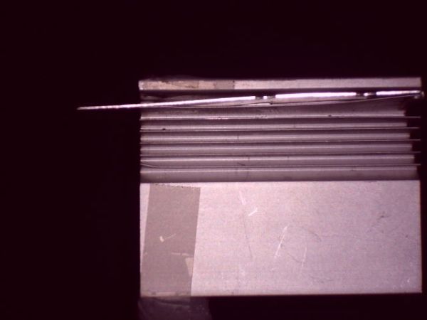
So I made a small jig out of an old X-Box heat sink, but you could use almost anything you can drill a precise hole into that won’t easily wear.
Drill a hole the exact size of the LED you are using. If the hole does wear or is a bit big, stick some tape over half the hole, and shove in an LED. You want the fit to be snug.
Mine would be snug enough that I added an aluminum “eject” lever as well to help pop the LEDs out of the jig.
I tried to loosen the hole up a bit, but then had to add tape because I widened it too much! LOL.
Step 2: The Better Way…put away the tape measure.
BEFORE YOU START – make sure the leads (legs) on your LEDs are 28 and 29mm in length. If they are shorter, your cube will be too small to use on the base boards you can get here.
Also, if you simply build the cube smaller and make your own base, if the leads are the shorter ones, you may find that you cannot see the LEDs in the back well, and animations that go all the way through the cube won’t look right because too many LEDs are in the way of the ones behind them.
If your LEDs are too short, see if the supplier will exchange them, but it’s best to check before paying for them first.
Bend the anode out so it is at the outer edge of the LED.
The LED goes in the hole you drilled anode up(opposite side from you), cathode down (closest to you) when you insert it.
Once the LED is firmly in place, bend the cathode directly to the right til it’s horizontal.
bend the anode straight forward til it’s also laying flat.
use snub nosed pliers and slide them down the anode til they hit the edge of the LED (the LED’s rim should be sticking above the aluminum block if the hole is fitted correctly).
Grip the anode, and bend straight back up, making sure the part against the LED stays there – meaning the anode should now be in an “L” shape, with the lower part of the “L” going from the edge of the LED to it’s origin.
The LED is now ready to be soldered into it’s layer.
Don’t forget that down one side of the layer, you will want the cathode bent from the edge of the LED into a laying down “L” shape with the top of the “L” pointed towards you.so that the row it is in can connect to the row below it.
These will interconnect the rows in the layer down one side of the layer, and the last LED will have it’s lead sticking out the end of the layer. This will be a convenient place later to connect the layer select line from that layer’s transistor.
In the magnified view, you can see how the anodes line up perfectly when soldered together in a column.
You solder them where they MEET – DO NOT overlap them at all. This way you don’t have to measure anything because they will always meet at the length of the anode from the outer rim of the LED.
Step 3: Assembly of the cube
This goes pretty much as CHR’s assembly, just with my improvement on how to bend the leads.
The other thing I did out of laziness, and lack of carpentry skill, was to use cardboard for the rig to solder the layers together.
Since my leads were 28 and 29 mm long…I figured take off a mm for bending, and maybe one more for good measure.
Well, I forgot to take the 1 more for good measure off, and had problems with gaps when soldering! LOL!
The idea would have been (and is), make a grid with 26 mm spacing, and print it out. The cathode leads should meet up when soldering them pretty much perfectly, or with a very small amount of overlap.
If your LED cathodes don’t meet up (there is a gap) then make another templateand get another piece of cardboard. Print out the template with the grid spacing reduced by 1mm.
If you make solder bridges to cover the gap, you may find the cube breaks easily.
Tape the grid to what will be your cardboard template. I used an old motherboard box.
***********************************************************************************************
NOTE: I HAVE NOW INCLUDED A PDF FILE OF THE TEMPLATE GRID FOR YOU TO PRINT OUT
***********************************************************************************************
Print 2 copies. You will need 1 for the template itself, and another to make the holes for the cube base.
Poke a pin at each intersection. This is like drilling a pilot hole. I used a large sewing needle.
Then find a philips screwdriver with a shaft about the diameter of your LEDs.
Poke this through each hole.
The first time you poke LEDs into these holes, they may be very tight when you first insert an LED – don’t worry, the rest of the layers will be easier afterward.
It’s better the holes be a bit too small than too big.
Since I bought 1000 LEDs and only needed 512, instead of straightening out some form of wire for the mid and left braces, I cut the leads off 7 (new unused) LEDs per layer and used the 14 cut leads as support braces.
Solder these in place before removing the layer from the cardboard template.
Once a layer is completed and soldered, and your braces put in place as well, you can poke the LEDs out of the holes from the bottom side of the cardboard. Do it gently and gradually – individual layers are fragile.
I included a photo of one of these layers compared to a spare layer I made for my original prototype cube.
Step 4: Assemble the layers
You can see how nicely the layers line up under each other during assembly. No need to try to curve the anodes around to connect to the next layer down. The end result is a near perfect cube.
You do need to of course line up each anode so it meets the top of the anode below it while soldering them together.
I don’t like joint stress, so I would bend each lead til it lined up with the lead below it without having to be held in place, then I would solder them together.
Line each anode so it just touches the anode below it. This eliminates any measuring or need for spacers to get the same distance from LED to LED (layer to layer) every time.
NOTE: I actually connect the layers with the anodes pointed towards me (cube on it’s side). The reason I keep saying “the layer BELOW it” is that you build the cube from the top down. Each layer you solder on, is the next layer down once the cube is upright.
I found that soldering the layers together while it’s on it’s side, I didn’t require any clamps etc. I would just tack a couple anodes in place, then proceed to solder them row by row.
Also included is a photo of box of pre-bent LEDs. I got into a groove and bent up all the LEDs I would need at one time (plus some), and then I would just pull them from the box and put them in the template to make a layer.
I made spares because you do run into the odd bad LED during testing.I find it much easier and faster to test the LEDs once they are bent and soldered in, simply from a time factor point of view.
Testing each LED before soldering it in is pointless, and gives you a false sense that all your LEDs are fine. Some may fail when you bend the leads, and others may fail from the heat of soldering. You will almost never see an LED fail right out of the bag. Bend, solder, THEN test, otherwise you will be testing them before AND after, which is a waste of time, especially when soldering this many LEDs.
IMPORTANT – test each layer while it’s still in the template, before soldering the layer it to the others. Once it is soldered to the cube, re-test it, then connect the cathode of the top layer, and touch each anode in the bottom layer to make sure your column connections are all good. Some LEDs may burn out during soldering, and some column connections may not get soldered properly, may have been forgotten, or the connection may have broken during the process. If an LED doesn’t light, test it individually in the cube before replacing it – it may simply have a bad solder joint. Make sure you didn’t bridge the LED leads together during soldering if it doesn’t light.
After the cube is completely assembled is NOT the time to find out you have a bad solder joint or burned out LED!!!
For more detail: CHR’s 8X8X8 LED Cube – Revisited with improvements!