Summary of ChronodeVFD: A Cyberpunk Wristwatch
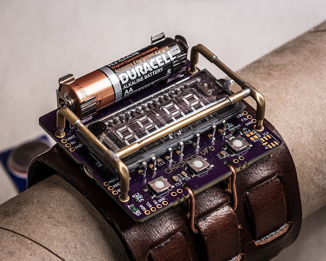
The ChronodeVFD is a DIY cyberpunk wristwatch utilizing an IVL2-7/5 VFD tube. The project addresses the challenge of powering a high-voltage display from a single alkaline battery, achieving 6–10 hours of runtime with AA cells. The design features a transparent tube allowing PCB visibility and integrates multiple sensors for future expansion.
Parts used in the ChronodeVFD:
- IVL2-7/5 VFD display tube
- Atmel ATMega88 AVR microcontroller
- Maxim DS3231 real-time clock
- Maxim MAX6920 12-bit shift register
- MCP1640 5V boost converter
- NCP1403 13.5V boost converter
- MMBTA42 NPN transistor
- Phototransistor (Q2)
- BMP180 barometric/temperature sensor
- MMA8653 accelerometer
- Alkaline AA or AAA batteries
- 6-pin FTDI serial block
The ChronodeVFD is a personal project I’ve been working on for a couple of months. It’s a wristwatch built around the IVL2-7/5 VFD display tube. I originally purchased a few of these tubes to build a standard desk clock, but after playing around with them, I realized I could probably build a wristwatch too. The tube has a number of features which make it more suited than most Soviet-surplus VFDs for this purpose.
- nominal 60mA filament current @ 2.4V, but still works with ~35mA @ 1.2V.
- It’s small — only 1.25 x 2.25″
- It’s flat, as opposed to the round tubes like the IV-18, which would be much clunkier in a watch design.
- can operate from a relatively low grid voltage of 12-13V (up to 24V)
- pulls only about 2.5mA/segment from the grid rail @ 12.5V. (“8” = 20mA)
One other feature that I like about this device is that unlike nearly every other VFD tube, the IVL2-7/5 has no opaque or diffuse backing behind the digits. It’s completely transparent front to back, which means that if you put it on top of a circuit board, you can (with a bit of backlighting) see the PCB below.
The single biggest constraint on a project like this is the power supply. Because this is a costume piece that I’d only wear occasionally, I decided I wouldn’t mind if the battery only lasted 6-10 hours. However, I didn’t want it to be uncomfortable to wear or excessively bulky, so my options for battery power were limited. Coin cells were out because the internal resistance was too high to meet the current requirements, so I was left with AA and AAA single cells. I decided to go with alkaline cells, since the lower nominal voltage of NiMH rechargables would mean an even lower efficiency for the boost converters, and less current for the filament. The finished project can be used with either 1xAA or 1xAAA alkalines (with the appropriate clips), however AAAs only last about 2 hours, so I’m sticking with AAs for now.
The Circuit
The circuit is pretty straightforward. The core is an Atmel ATMega88 AVR, and the real-time clock is a Maxim DS3231. The DS3231 is nice because it’s an all-in-one solution: it has a 32kHz temperature-compensated crystal and capacitors built in, so the only external component required is the backup battery. However, the DS3231 is pretty expensive. I happen to have a tube of them left over from another project, so I decided to use it in this design. There are other, much less expensive RTCs available which would work quite as well (BYO crystal, though).
The VFD display is driven by a Maxim MAX6920 — a 12-bit shift register with high-voltage (up to 76V) outputs. The 12-bit field is designed specifically for driving 4-digit clock displays (4 digit channels and 8 segment channels). It’s easy to use and very reliable and compact. It really is the only chip of its kind, so it’s a tad expensive. It’s also possible to drive the VFDs using a bunch of discrete components, but that was impractical here due to space constraints. If you’re interested in that, you should check out Riad Wahby’s excellent inGrid clock build, which describes his discrete HV driver circuit in some detail.
The circuit is powered from 3 voltage rails. The first is the battery voltage itself, which is used to drive the display filament (switched by the micro with a low-side MMBTA42 NPN). The battery voltage also feeds into the 5V boost converter (MCP1640 SOT23-6), which drives the #2 rail. This 2nd rail powers the AVR, DS3231, and MAX6920 logic, as well as acting as the input voltage to the second boost converter (NCP1403 SOT23-5), which produces the 13.5V VFD grid voltage (the third rail). The NCP1403 is enabled/disabled by the microcontroller, so it’s only in operation when the display is lit, which helps limit current draw from the battery.
I included jumpers (0805 pads) on the board so that I could switch the filament power from the battery to the 5V rail, in series with a current limiting resistor. In this configuration, the filament stays at a steady brightness for the life of the battery, and the display is brighter. However, the load on the 5V rail is higher, and considerable power is wasted as heat through this resistor, so the battery life is significantly shortened.
Also included on the board are a number of sensors: one analog and two digital. The analog sensor is a phototransistor used to detect the ambient light level (Q2). The digital sensors include a BMP180 barometric/temperature sensor and a MMA8653 accelerometer, to detect movement. Neither of these are populated in the photos above, though I may decide to add them in the future. Both digital sensors share the I2C bus with the DS3231, and an I2C breakout is provided on the bottom-left edge of the board, for troubleshooting or expansion purposes.
Other headers on the board include a 6-pin FTDI serial block, breakouts for two AVR ADC inputs (one is used by Q2), and test points for the battery voltage and boost converters. The AVR ISP 6-pin header is on the underside of the board beneath the display, to allow programming after assembly is complete.
For more detail: ChronodeVFD: A Cyberpunk Wristwatch
- How does the filament power configuration affect brightness?
Switching filament power from the battery to the 5V rail via a resistor maintains steady brightness but significantly shortens battery life due to heat waste. - Why were coin cells not chosen for this project?
Coin cells were rejected because their internal resistance was too high to meet the current requirements of the VFD. - What is the primary reason for using alkaline cells over NiMH rechargables?
Alkaline cells were chosen because the lower nominal voltage of NiMH would result in lower efficiency for the boost converters and less current for the filament. - How long do AAA batteries last compared to AA batteries in this watch?
AAA batteries only last about 2 hours, whereas the project is designed to run for 6–10 hours on AA alkalines. - Does the IVL2-7/5 tube have a backing behind the digits?
No, the tube is completely transparent front to back with no opaque or diffuse backing. - What component drives the VFD display in this circuit?
The display is driven by a Maxim MAX6920, which is a 12-bit shift register capable of high-voltage outputs. - Can the real-time clock be powered without external capacitors?
Yes, the Maxim DS3231 includes a temperature-compensated crystal and capacitors built-in, requiring only a backup battery externally. - How is the 13.5V grid voltage managed to save power?
The NCP1403 boost converter producing the grid voltage is enabled and disabled by the microcontroller so it only operates when the display is lit.