In this project, we will go over how to build a heat detector circuit using an Arduino.
A heat detector circuit is a circuit, of course, which can detect the presence or absence of heat.

This could be useful for a wide range of circuits including any device that needs monitoring and protection from excess heat. When excess heat is given to a circuit, maybe this could be dangerous for the circuit. Thus, if too much heat is detected, we can make it so that an alarm, either light or sound, is triggered, telling us that the circuit is being exposed to a dangerous amout of heat.
In our circuit for this project, when a certain threshold is heat is reached, an LED will turn on, alerting us to this situation.
The device we will build in this project will be automatic in nature. As soon as the heat reaches a certain threshold, the LED attached to our arduino board will turn on right away, automatically.
For this project, the main component we will use is a thermistor. A thermistor’s resistance varies based on the amount of heat that it is exposed to. In room temperature, an NTC (negative temperature coefficient) thermistor will have a resistance near its rated resistance value. So, for example, a 100KΩ thermistor will have near 100KΩ of resistance. However, if the thermistor is exposed to heat, its resistance will drop significantly, to below 40KΩ. We can exploit its varying resistance properties to determine if our circuit is being exposed to a high level of heat or if it isn’t. If the thermistor’s resistance is very high, it is exposed to a low level of heat. If it is very low, it is exposed to a high level of heat.
When we place a thermistor in series with a resistor, a voltage divider is formed. Voltage will be allocated to the 2 components based on the each one’s respective resistance. More voltage will fall across the component with the greater resistance, according to ohm’s law, V=IR. This is the principle in this circuit we exploit to determine the heat level that our circuit is exposed to and this will determine whether our LED turns on or off.
Components Needed for the Heat Detector Circuit
- 100KΩ NTC Thermistor
- 20KΩ Resistor
- Arduino
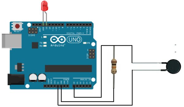
Heat Detector Circuit Schematic
The schematic for the heat detector cirucit is shown below:
Code
The code to turn on an LED when the heat detector level rises above a certain threshold is shown below.
const int ledPin=13; //the code will flash the LED connected to pin 13
const int sensorPin= 0; //Sensor pin connects to analog pin A0
For more detail: How to Build a Heat Detector Circuit Using an Arduino