In my previous Instructable I have described how to plug the ESP-01 module into a breadboard.
This is just the first step to make a cheap Arduino WiFi shield using the ESP8266 module. With few more electronic components and the WiFiEsp library you can build it for less that 10 USD.
Step 1: Components
Here are the components you need
- Arduino board – In this example I’m using an Arduino Uno board but I personally uprefer using an Arduino Mega because it has more memory and has a second serial port to communicate with the ESP module.
- ESP-01 – This is the smallest and cheaper type of ESP8266.
- AMS1117 5V to 3.3V Power Supply – Arduino boards are typically powered at 5V while ESP8266 needs a 3.3V power source. The Arduino 3.3V output pin cannot provide the power needed by the ESP (up to 250mA). This can be solved using a 3.3V voltage regulator like the LM1117/LD1117 or AMS1117.
- Breadboard – A 170 holes mini breadboard is enough but you can use a bigger one if you need.
- 10 uF Capacitor – A small electrolytic capacitor is needed to stabilize the voltage regulator. Any 10-100 uF should be ok.
- 2 resistors (1K and 2.2K) – A simple voltage divider is needed to shift down the 5V output of the Arduino TX pin. You can use other resistors as long as they are in a 1/2 ratio approximately.
- Jumper wires
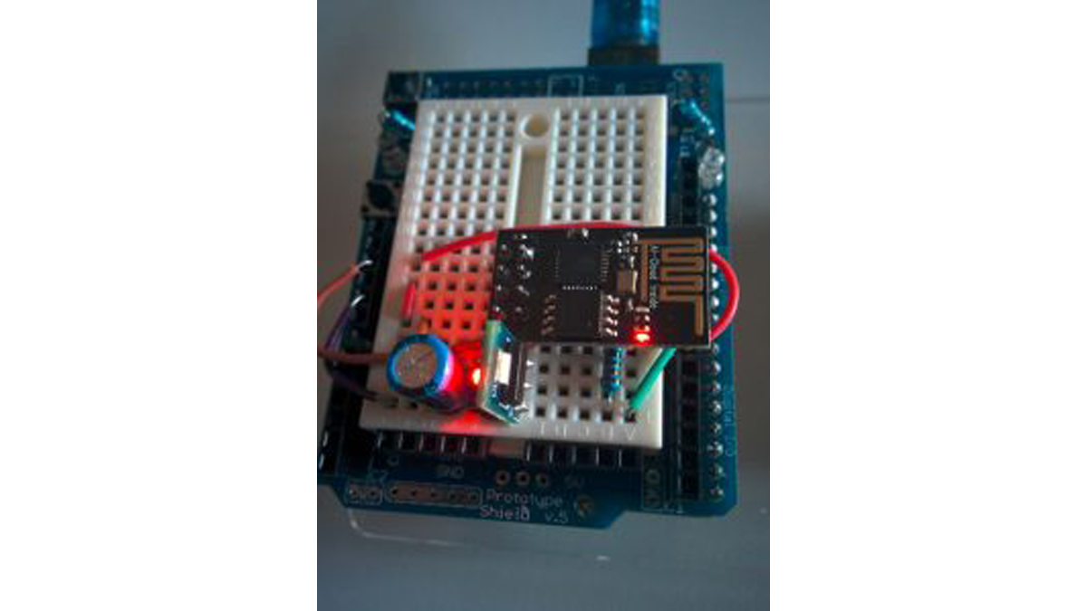
Step 2: Wiring It Up
In the schematic I have described how to connect all the components using an Arduino Uno board and a mini breadboard.
- The ESP’s VCC pin is powered by the 3.3V output pin of the voltage regulator (AMS1117 in my example). The 10uF capacitor is connected to the output pins to stabilize the regulator. The CH_PD pin must also be connected to 3.3V. The GND pin is obviously connected to ground.
- The ESP’s TXD pin can be connected directly to the RX pin of Arduino (emulated on pin 6).
- The ESP’s RXD pin is connected to the TX pin of Arduino (emulated on pin 7) through the level shifter.
If you are using an Arduino Mega you need to change the wiring schema an connect the ESP TX/RX pins to the Arduino Serial1 pins. This allows to have a more fast and reliable communication link between the Arduino board and the ESP-01 module.
Step 3: Testing
To test the shield you can use the following Arduino sketch. Note that the sketch is emulating the Serial1 interface if it is not available.
Read more: Cheap Arduino WiFi shield with ESP8266