Summary of Cheap Arduino Controlled Light Sockets – Reverse Engineering RF
Smart lightbulb kit hacked to control unlimited channels by extracting RF codes from the bulb holder EEPROM and retransmitting them with an Arduino and 315MHz RF transmitter. Guide covers opening the socket, locating the 24C04 EEPROM, wiring it to a Bus Pirate for I2C dumps, verifying unique bytes per bulb, and preparing data for Arduino-based RF transmission. Total cost about $19 for four sockets plus ~$20 for transmitter; time 1–2 hours.
Parts used in the Smart lightbulb kit hack:
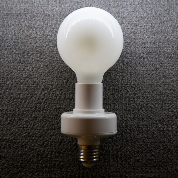
- Vktech Wireless Light Bulb Holders (4-pack)
- Arduino Uno or similar
- 315MHz RF Link Transmitter
- Bus Pirate (Sparkfun version used)
- 24C04 EEPROM (on bulb PCB)
- IC clips/hooks
- Small Phillips screwdriver
- Computer with micro USB cable
- Breadboard and spare solid core wire
Smart lightbulbs cost your firstborn child. Which is a shame, because smart lights unlock tremendous potential for home automation, energy savings, and all sorts of cool projects.
If only there was a way to control your lights without breaking the bank…
And now there is! For $19 on Amazon, you can get a 4-lightbulb kit from China that ordinarily is limited to 4 channels from a single remote…but with some creative hacking, can be used to control an unlimited number of channels using an arduino and a very simple RF module!
Here’s a video of them in action as part of our smart bathroom project (Instructable for that coming soon!):
Think this is awesome? Don’t forget to favorite it and follow us on Facebook!
Time required: 1-2 hours
Total Cost: $19 for four sockets ($5/socket), ~$20 for a transmitter
You should know:
Materials:
- A 4-pack of Vktech Wireless Light Bulb Holders
- Arduino Uno or similar
- 315MHz RF Link Transmitter
Tools:
- IC Clips/hooks
- Bus Pirate (we used the sparkfun version)
- Small Phillips screwdriver
- Computer with a micro USB cable
- A breadboard and spare wire (solid core is best)
Step 1: Reading the EEPROM
We’ll start by cracking open one of these light sockets and reading its memory. Grab your screwdriver and remove the two phillips screws holding the housing together. The case should fall open and reveal the PCB inside.
If you look around, you’ll see a few capacitors, some diodes, a big box (the relay), a long IC (the microcontroller), a separate board tacked on (the RF receiver), and a little 8-DIP chip marked 24C04 – this is the EEPROM that stores the RF command to turn on the bulb.
Let’s take a closer look at what the memory chip holds, shall we? Using the bus pirate and the datasheet for the EEPROM chip, wire up a circuit like the one shown. You should have:
- Bus Pirate VCC -> chip VCC (and to VPU, the pullup pin of the Bus Pirate)
- Bus Pirate GND -> chip GND
- Bus Pirate SDA (MOSI, Orange for Sparkfun BPs) -> chip SDA
- Bus Pirate SCL (CLK, Yellow for Sparkfun BPs) -> chip SCL
- Bus Pirate VPU -> Bus Pirate VCC (the pullup I/O pins are driven from this pin)
Next, let’s run a script that will dump the EEPROM data to a file using the I2C circuit we just set up. Using the terminal or command line, navigate to the folder where you downloaded i2c_dump.py and run it as follows:
It’ll produce a .hex file showing the hex values of the data.
Open up the .txt file. If it contains nothing but 0x00 or nothing but 0xFF, chances are you need to check your circuit and re-run the dump. If you see a few different values towards the start of the file and a bunch of 0x00’s after, you have a successful hex dump!
It’s a good idea at this point to try dumping a couple of the other bulbs to see what values change in this code. Don’t worry if the hex dumps don’t make sense yet, but you should notice that only one specific value in them is changing. Hmmmm…
For more detail: Cheap Arduino Controlled Light Sockets – Reverse Engineering RF
- What is the goal of this project?
To control an unlimited number of light channels by reading RF codes from cheap bulb holders and retransmitting them with an Arduino and RF transmitter. - How much does the hardware cost?
The 4-bulb kit costs $19 and the transmitter is about $20 according to the article. - What skills should I have before starting?
You should know how to program an Arduino and the basics of using a Bus Pirate. - What component stores the RF command in the bulb holder?
An 8-DIP chip marked 24C04 EEPROM stores the RF command. - How do I read the EEPROM data?
Wire the EEPROM to the Bus Pirate using I2C (VCC, GND, SDA, SCL, VPU) and run i2c_dump.py to produce a hex file. - What indicates a successful EEPROM dump?
The hex file shows varied values near the start and many 0x00s after; if it's all 0x00 or all 0xFF, recheck the circuit. - Do different bulbs have different data?
Yes; dumping multiple bulbs shows one specific value changing between dumps. - What tools are needed to open the bulb holder?
A small Phillips screwdriver is used to remove the housing screws and reveal the PCB.