Summary of 9 Degrees of Freedom – IMU
Summary: I built a low-cost, single-sided PCB milled 9DOF IMU inspired by Sparkfun's board, using an ITG-3200 gyro, LSM303 accel/magnetometer, and an ATmega328P MCU. All code, schematics, and milling files are on GitHub. The design targets hobbyist-friendly CNC milling and costs roughly $20 in electronics.
Parts used in the 9DOF IMU:
- ITG-3200 3 Axis Gyro
- 4.7K resistor (x2)
- 0.1uF capacitor (x4 total across sections)
- 10nF capacitor
- 2.2nF capacitor
- LSM303 3 Axis Accelerometer/Magnetometer
- 10uF capacitor (x2)
- 4.7uF capacitor
- 0.22nF capacitor
- Atmega328P Microcontroller
- 10K resistor
- Tact switch
- 8MHz resonator
- Green LED (optional)
- 1K resistor (optional, x2 listed)
- 6 pin surface mount ISP header
- 6 pin through hole FTDI header (and optional extra through hole headers)
- Red LED (optional)
- 0 Ohm resistor jumpers (x9)
- 10mil carbide endmill (for fine features)
- 1/64 inch endmill (for most traces)
- 1/32 inch endmill (for board outline)
- FR-1 machinable single sided PCB blank
- Solder
- Soldering iron
- Heat gun
- Flux pen
- Tweezers
- Multimeter
- 3.3V FTDI cable or board
- ISP programmer or Arduino configured as programmer
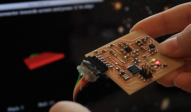
I’m working on a project that requires full orientation information, so I built an Inertial Measurement Unit from scratch. I really like the 9DOF IMU board that Sparkfun makes – the calibration code that comes with it is fantastic – but I wanted to redesign the board so that it could be made at a much lower price using a single-sided PCB mill. I think the electronics come out to about $20 for this project. All the code, schematics, and PCB milling files are up on github (click the cloud-shaped button to download).
Here’s what it does:
PARTS LIST:
Gyro:
(x1) ITG-3200 3 Axis Gyro Component Distributors Inc ITG-3200 Sparkfun SEN-09793 Newark 37T8091
(x2) 4.7K resistor Digikey P4.7KECT-ND
(x2) 0.1uF capacitor Digikey 1276-1017-1-ND
(x1) 10nF capacitor Digikey 1276-1035-1-ND
(x1) 2.2nF capacitor Digikey 1276-1288-1-ND
Accelerometer/Magnetometer:
(x1) LSM303 3 Axis Accelerometer/Magnetometer Digikey 497-13819-1-ND
(x1) 10uF capacitor Digikey 1276-2876-1-ND
(x1) 0.1uF capacitor Digikey 1276-1017-1-ND
(x1) 4.7uF capacitor Digikey 587-2994-1-ND
(x1) 0.22nF capacitor Digikey 1276-2759-1-ND
AVR:
(x1) Atmega328P Microcontroller Digikey ATMEGA328P-AURCT-ND
(x1) 10K resistor Digikey P10KECT-ND
(x1) tact switch Digikey SW262CT-ND
(x2) 0.1uF capacitor Digikey 1276-1017-1-ND
(x1) 8MHz resonator Digikey 535-10004-1-ND
(x1) green LED (optional, but will help with debugging) Digikey 160-1404-1-ND
(x1) 1K resistor (optional, but will help with debugging) Digikey P1.0KECT-ND
Interface:
(x1) 6 pin surface mount ISP header Mouser 649-95278-101A06LF
(x1) 6 pin through hole FTDI header Mouser 571-3-644456-6
(I included two additional rows of through hole headers in my PCB to make mounting the board easier, in this case you will need 3 of the through hole 6 pin headers. This is optional)
Power
(x1) 10uF capacitor Digikey 1276-2876-1-ND
(x1) 0.1uF capacitor Digikey 1276-1017-1-ND
(x1) 1K resistor (optional, but will help with debugging) Digikey P1.0KECT-ND
(x1) red LED (optional, but will help with debugging) Digikey 160-1405-1-ND
Other:
(x9) 0 Ohm resistor (jumpers) Digikey P0.0ECT-ND
Milling:
(x1) 10mil carbide endmill Carbide Depot CU 222737 (for the tiniest features on the board)
(x1) 1/64″ endmill Carbide Depot CU 129974 (for milling out most of the traces)
(x1) 1/32″ endmill Carbide Depot CU 129985 (for cutting out the board)
(x1) FR-1 machinable single sided PCB blank Inventables 24201-02
I used a Roland Modela for the milling, though I believe this could be done on a Shopbot Desktop or similar machine as well.
Other Supplies
solder
soldering iron
heat gun
flux pen
tweezers
multimeter
3.3V FTDI cable Digikey 768-1015-ND or board Sparkfun DEV-09873
(you may be able to use an Arduino as an FTDI connector, but I’m not sure this will work with the 8Mhz clock)
ISP programmer (or use an Arduino or make your own – 6 pin connector and ribbon cable)
For more detail: 9 Degrees of Freedom – IMU
- What sensors are used in this 9DOF IMU?
The project uses an ITG-3200 3 axis gyro and an LSM303 3 axis accelerometer/magnetometer. - Can this board be made on a single-sided PCB mill?
Yes, the redesign is targeted for manufacture on a single-sided PCB mill using FR-1 machinable blanks. - How much do the electronics cost approximately?
The electronics are estimated to cost about $20 for this project. - What microcontroller is used?
The project uses an Atmega328P microcontroller. - What milling tools are recommended?
Recommended cutters are a 10mil carbide endmill for fine features, a 1/64 inch endmill for most traces, and a 1/32 inch endmill for cutting out the board. - Is the project code and PCB files available?
Yes, all code, schematics, and PCB milling files are available on GitHub via the project link. - What interface headers are required?
The board uses a 6 pin surface mount ISP header and a 6 pin through hole FTDI header; additional through hole headers are optional for mounting. - What power and debug components are suggested?
Suggested power and debug parts include 10uF and 0.1uF capacitors, optional red and green LEDs with 1K resistors, and 0 Ohm resistor jumpers. - What equipment is needed for programming and serial communication?
An ISP programmer is required for flashing or an Arduino used as a programmer, and a 3.3V FTDI cable or board is used for serial communication.