First of all,
this is my first Instructable, and I’m not a native English speaker (or writer), therefore I apologize in advance for the overall low quality . However, I hope that this tutorial can be helpful for people using a heart rate (HR) monitor system (composed by a chest strap belt transmitter and a receiver watch) and who either:
- want to know exactly which battery needs to be replaced (inside the belt or inside the receiver watch), when the system stops working properly. Usually, just to be sure the user ends up changing both batteries, even though the one in the belt is subjected to a heavier load and therefore discharges faster than the other one
or
- are interested (as I am) in developing a heart rate data logger for further evaluations – for instance for the statistical analysis of the HRV (Heart Rate Variations) in static conditions, or for correlation studies among HR and physical efforts in dynamic conditions – and prefer to use a chest strap belt (Cardio) simulator rather then to wear a real one all the time during the test phases.
For the reasons above I called my Instructable “CardioSim”
Step 1: How Does It Work
The wireless transmission of the heart rate pulses between the transmitter (chest strap belt) and the receiver (dedicated watch, as well as running treadmills, workout devices, etc.) is based upon a Low-frequency magnetic communication (LFMC), and not a traditional Radio-Frequency.
The standard frequency for this type of (analog) monitoring systems is 5.3kHz. New digital systems are based on Bluetooth technology, but this is out of the scope of this tutorial.
For those who are interested in deepening the topic, a comprehensive description of the LFMC technology, including the pros and cons vs. RF, can be found on this App note
http://ww1.microchip.com/downloads/en/AppNotes/002…
However, for the sake of this project, be sufficient to know that a 5.3kHz magnetic field carrier generated by a LC (series) resonant circuit is modulated on the base of a simple OOK (On-OFF Keying) format, where each heart pulse switches the carrier On for about 10ms. The signal is detected by a (parallel) LC resonant tank (with the same resonant frequency of the magnetic field, and provided that both coils are properly aligned) , amplified and sent to the measuring unit.
Although in the WEB some examples of the receiver circuit can be found, I wasn’t able to find a model for the transmitter, so I decided to analyse the signal generated by my chest belt, and build a circuit that can simulate it, with a similar field strenght, frequency, and format.
Step 2: Schematic and Parts

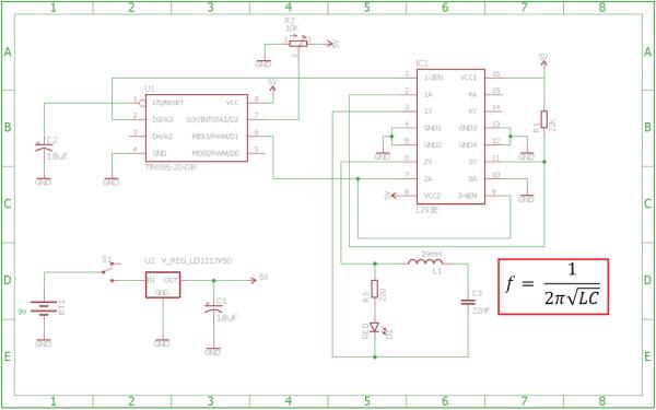
The circuits is composed by very few components that can be fit in a small case:
- Case with strip board, like this one
- High density foam strip, 50x25x10mm (like the one used for ICs’ packaging)
- Microcontroller ATTiny85-20
- Motor Driver L293
- Voltage regulator 5V, typ 7805 or LD1117V50
- 2x Electrolytic Capacitor 10uF/25V
- Capacitor 22n/100V
- Trimpot with shaft,10K, 1 turn, (like in Arduino Starter Kit)
- Resistor 22K
- Resistor 220R
- LED red 5mm
- Inductance 39mH, I used a BOURNS RLB0913-393K
- 9V battery
- mini SPDT switch (I recycled the AM/FM switch from an old transistor radio)
The most important component is the inductance, a high quality ferrite core and low resistance are mandatory to keep it small and to obtain a good Quality Factor of the resonant circuit.
Step 3: Circuit Description & Code
Applying the formula of the LC circuit shown in the drawing, with L = 39mH and C=22nF the resulting frequency is around 5.4 kHz, which is close enough to the standard value of 5.3 kHz. The LC tank is driven by a H-bridge inverter composed by the 2 half bridges 1 and 2 of the motor driver IC L293. The carrier frequency is generated by the TINY85 microcontroller, which also drives the modulating signal simulating the HR. Trough the Trimpot attached to the analog input A1 the Heart Rate can be changed from about 40 to 170 bmp (beats per minute) – which in real conditions is considered adequate for most amateur sportspeople. Since the bridge needs to be driven by two opposite square waves (and with my limited knowledge of the ATTiny’s Assembler code I was able to generate only a single one), I used the half brige 3 as an inverter.
For these simple tasks the internal clock @ 16MHz is adequate, however I previoulsy measured the needed calibration factor for my my chip and put it the command line “OSCCAL” in the setup section. To download the sketch to the ATTiny I used an Arduino Nano loaded with the ArduinoISP code. If you are not familiar with these two steps there are tons of examples in the Web, if someone is interested I developed my own versions that I can provide on request. Attached the code for the ATTiny.
Step 4: Assembling the Circuit

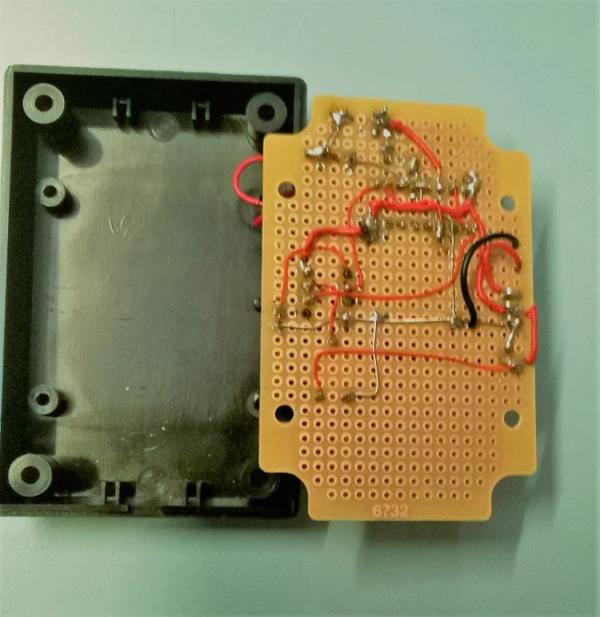
The case had already a 5mm hole on the top cover that was perfect for the Led, and I only had to drill a second 6mm hole, aligned with the first one, for the shaft of the trimpot. I arranged the layout of the components in such a way that the battery is hold in place between the trimpot and the TO-220 voltage regulator, and firmly blocked in its position by the foam strip glued to the top cover.
As you may notice, the inductance is mounted horizontally, t.i. with its axis parallel to the board. This is under the assumption that the receiver inductance is also lying in the same direction. In any case, for optimal transmission, always ensure that both axes are parallel (not necessarily on the same spatial plane) and not perpendicular to each other.
At the end of the assembling check thoroughly with a circuit tester all connections with a circuit tester.
Step 5: Test the Circuit
The best test tool for the circuit is a HR monitoring receiver watch:
- Lay the watch next to the CardioSim.
- Set the trimpot in the middle position and switch on the unit.
- The red LED should start flashing at about 1 sec intervals (60bmp). This indicates that the LC resonator tank is properly energized and working. If this is not the case, double check all connections and welding points.
- If not already automatically on, switch on the watch manually.
- The watch should start to receive the signal showing the measured HR.
- Turning the trimpot to the end position in both directions to check the full HR range (+/-5% tolerance of the range limits is tolerable)
All steps are shown in the attached video
Step 6: Warning
As final safety advice, be aware that the LFMC implemented in this simple format doesn’t allow to address different units in the same field range, that means that in case both the CardioSim and a real measuring belt are sending their signals to the same receiver unit, the receiver will be jammed, with unpredictable results.
This can be dangerous in case you are going to increase your physical performance and maximize your efforts on the base of the measured HR. CardioSim is intended to be used only for testing of other units and not for training!
That’s all, thanks for reading my Instructable, any feedabck is welcome!
Source: CardioSim
