Recently I saw a documentary about the history of the television. And to my surprise they showed that there existed a mechanical television before the well known CRT televisions.
Those mechanical televisions or televisors were pretty smart and simple.
A CRT is simply an electron beam that scans a surface covered with a luminescent phosphor line by line. And the intensity of the beam is then directly proportional with the whiteness of that particular spot on the screen.
A televisor works in a very similar way. But instead of an electron beam, holes are used. Holes in a spirally pattern on a disk scan a small area as the disk rotates. After that particular area an electrical lamp varies its intensity. Bright means a bright spot wherever a hole is located.
There are some videos on youtube from people who have built other televisors. With more lines and far better image quality than this one. (but they aren’t made out of cardboard)
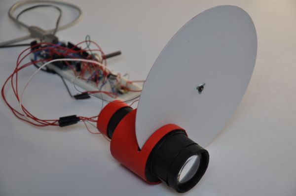
This instructable documents the build of such a very small 24 line televisor completely from scrap cardboard, scavenged electronic parts a laptop and an arduino.
The image quality is very, very low but it is built out of cardboard and it has only 24 lines.
But it was a fun build.
If you want a good display, there are much better alternatives, (pretty much everything is a better alternative).
As you will see, my technical skills are quite limited and hence the final result is limited too. A lot of things that I did here were a first for me so I had to improvise and will have missed out on probably much more efficient solutions. So, expect some very naive approaches.
But the final result kind of works and can display something in a recognisable way. (But that’s about it)
I have updated some things and mentioned what could be done better.
This is the general structure of the instructable:
Step 2-8: Building the cardboard hardware of the televisor.
Step 9: Building a led lamp.
Step 10: Making a speedometer to register the rotating speed of the disc.
Step 11: Writing a program to convert normal photo’s/images to a sound file. (to modulate the lamp)
Step 12: The electronics.
Step 13: Arduino to control the speed of the disc.
Step 14: Results
Step 1: The materials
The body
The Device itself is made out of white, pressed cardboard.
Most of it is of 0.8 – 1 mm thick. This cardboard is easy to cut and quite strong.
The disc
The disc is also made out of cardboard but a thicker and stiffer piece. ~1.6 mm thick.
However I think it would be best if something else is used such as wood or plastic. Because this cardboard likes to flex and bend and as you will see the disc must enter in a narrow split and this bending can cause friction.
The electronics
Three simple circuits are made. Two require a MOSFET to switch the larger currents.
A single rail op amp is used to amplify the audio signal.
More on the electronics in step 12.
LEDs are used as the light source of the televisor.
An Arduino
An arduino is used to control the motor speed.
A laptop
To convert images to audio and play them to drive the LEDs.
Step 2: The disc
An important part of the televisor is the disc.
As mentioned in the intro, the disc has several small holes and each one scans a line of a certain area as they pass over a small window (see next step).
To maximise the usable size of the window it is most convenient to place the holes in the area close to the edge of the disc. Each hole is made on a different concentric circle with a small phase difference in such a way that as the disc turns, only one hole is visible at a time in the window.
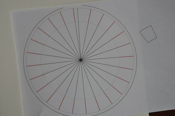
I have used inkskape to make a template to easily locate the positions of the holes.
The radius of the disc is 20 cm since that is about the largest size that can be printed on A4 paper.
The disc has 24 holes each separated with a phase of 14.8° because this makes the interval between the last and first hole a bit larger than the rest. The original idea was to make a camera and the consistent, periodic dark interval could have been used to recognise the transition to a new frame image. But in the case of the televisor it is mostly useless, but it can ease with manually tuning the rotation speed of the disk.
The locations of the holes are marked by a series of 24 red circles. This series is then rotated 14.8° repeatedly. Note that in each set of red dots only one hole should be drilled. The others should be ignored . (counting is less work than deleting all those extra unused dots)
This template is printed out (don’t convert it to jpg or an other non-vector format because the dots are so small that they will be blurry if you print them.) and cut out.
With a compass, a circle of the same size is drawn on a piece of cardboard. 1.6 mm thick Mat cardboard. (it is maybe better that something stiffer than cardboard is used for the disc) and this is cut out too.
The template is placed on top of the disc and secured with some tape.
Each hole must represent one line of the image, so each hole must be on a different concentric circle. The most convenient is a spiral pattern (it is not per se required, but if not, thenthe order must be remembered). So, in the first line the first dot is marked , the second line the second dot …
The marking happens by pressing a needle point in the dead centre of the dots.
The visible indentations made by the needles can now be used to drill out the holes.
The disc must of course spin around. This will be done with the aid of a small electro motor. A broken propeller was still attached to the motor and the extension used to keep the propeller on, could be used to attach the disk.
(I have also uploaded the svg file, you can find it below)
Step 3: The window
The disc will turn and the holes will pass in front of a small window. Behind the window a lamp (see further) is located which will shine trough the window via hole that is located there to the observer. The brightness of the lamp then directly translates into the brightness of the spot of the image where ever the hole happens to be located at the time.
First of all, the window is not per sé necessary. But if the window is not present, the image is just repeated (and shifted a line) above and below the middle image. Look here for an example of that. The televisor in that video is in color and is very good. Don’t expect that good quality for my small televisor.
The purpose of the window for me is to keep the light somewhat contained and to eliminate those extra frames.
Remember the small extra shape in the template of the previous step, this is the shape of one frame and thus the ideal window. Due to the fact that the holes move on circular paths, the shape isn’t rectangular but rather cut-off circle segments. In this way each hole traverses the area in the same amount of time. (it is easier to modulate the image in this way than to calculate in variable traversing times. And in the primitive way I convert images later on, this will cause some distortion, mainly due toe the fact that my disc is so small).
The frame of the window consists out of two circular discs (the shape is completely arbitrary) each 5.5 cm in diameter in which the cut-off circle segment shape is cut out. Note that I have elongated the shape a bit towards the centre. This can be done without problems. The vertical (left and right) boundaries are defined by the extension of the holes. The horizontal (top and bottom) ones are not (because the holes turn on a disc).
Two of these disks are needed. One in front and one behind of the spinning disc and the windows themselves must be aligned.
They are painted black to reduce internal reflections (that was mainly a concern when I still intended it to be a camera).
The disc must be free to spin between those windows so, the outer edge of the spinning disc is marked and a moon shaped spacer is made (4.5 mm thick in my case) so that the two discs can be glued together with much room for the free movement of the spinning disc.
Look at the pictures to actually intuitively know what all this explanation is about.
Note that in the final result only one hole is visible in the window and that all holes systemically scan the surface of the window. (or rather a part of it since I extended the window)
Step 4: The motor holder
The motor that spins the disc must of course be secured to something.
For this, some sort of arm is made. This arm will extend from a yet to be made main body (that holds the window) to the motor.
Forgive me, but for this thing I did not measure a lot, it grew more or less organicly and I shaped as it seemed fit at the moment.
And it is by far not the most efficient form.
Look at the schematic in the pictures, this step concerns the green stuff. The schematic should bring over the ideas that went in this arm.
The general picture is this:
A small cylindrical hole that holds the motor is required (the shape of the hole is completely dependent on the geometry of the motor. And a large cylindrical hole is needed trough which the internal structure and light of the televisor will go. The only requirement is that the window is entirely visible trough it (I have cut a bit of the ‘finer’ part of the window since the window is too large there). See next step to see what happens with the larger tube.
The small holes should fit tightly around the motor so that he needn’t be glued in, but is held there by friction alone.
Three of these shapes are made with each large hole the same size. The smaller holes depend on the geometry of your motor.
Look at the pictures, especially the schematic. The schematic is not exactly to scale but contains all elements. (except the spacers)
1 Blue = window
2 Green = motor arm
3 Pink = motor
(used in next step)
4 Black = tube
5 Orange = tight fit rings
6 Yellow = disc
For more detail: A cardboard televisor (with arduino and LEDs)