The principal behind ArduinoPi
First a little clarification, the ArduinoPi isn’t really a library or a command set or an out of the box controller, its more a proof of concept using already know programming languages. If you want to use it be ready for some PHP, CSS, HTML, C++ and jQuery!
The principal is as follows: The Arduino is connected as a slave device, meaning it waits for a command, execute it and maybe return a value or something. Everything must be initiated from the web browser. A true slave device.
It’s also possible for the Arduino to execute its own program and the ArduinoPi can then be used as a controller to switch variables. For example I have an automatic light switching system but using the ArduinoPi controller and my web browser I’m able to manually override it. ## The command set of the ArduinoPi
The Arduino will check for a valid command. Every command starts with @ and ends with :, variables can be separated with a comma. Of course other commands can be added yourself, I’ve found that these are the basics and cover enough to make some interesting interfaces.
Basic Switch-port-high command
@6,255:
This command is sent to the Arduino, for example this will switch port 6 high (255 = HIGH). The first value in this command must be between 0-99, which corresponds to the port number. Note that there is no checking so always see the port is set in OUTPUT mode and you are addressing the right port.
RGB Command
I’ve also added a RGB command for LEDs, this is a special command and is constructed as follows:
@101,245,23,0:
The 101 indicates the special command mode and the following 3 values are just the RGB values. In my example setup I’ve added 3 RGB LEDs and they all get turned on to the right value using the RGB command.
Read Sensor Command
The last command is the sensor command. It will read an analog sensor value and return it to the PHP script.
@102,6:
The 102 indicate a special command and the following value indicates the port that should be read using analogRead().
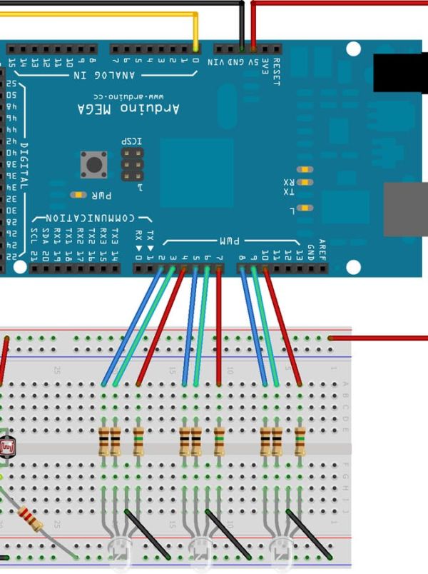
My test setup for the ArduinoPi
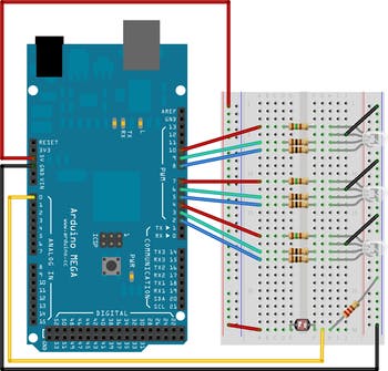
My test setup for the ArduinoPi
I’ve used the following components for testing various functions: 3 RGB LEDs + resistors and a light sensor. The example will work with the following configuration. The image does not contain the connection setup with level converter circuit from last time (to cut some space).