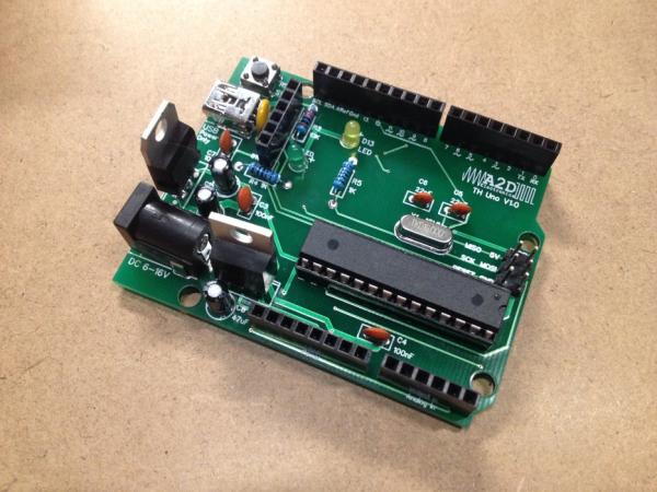
Summary of Building a DIY Arduino on a PCB and Some Tips for Beginners
This article guides users through soldering a DIY Arduino kit from A2D Electronics. It details the assembly process, including tips for handling components like pin headers and IC sockets to ensure proper alignment. The guide explains the function of each part, such as using specific resistors for LEDs and capacitors for power smoothing, ensuring the board operates at full 16MHz speed with an external oscillator.
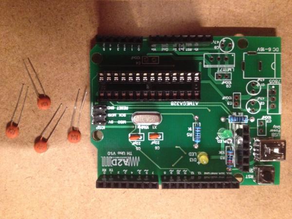
Parts used in the DIY Arduino:
- Mini USB Connector
- Female Pin Headers (6pin x2, 8pin x2, 10pin x1)
- Male ICSP Header (3x2)
- 28pin IC Socket
- AtMega328P Microcontroller
- Resistors (two 1K ohm, one 10K ohm)
- LEDs (2 units)
- Crystal Oscillator
- 22pF Ceramic Capacitors (2 units)
- Reset Switch
- 100nF Ceramic Capacitors (4 units)
This is meant as a guide to anyone soldering their own Arduino from a kit, which can be purchased from A2D Electronics. It contains many tips and tricks in order to build it successfully. You will also learn about what all the different components do.
Read on and learn what it takes to build your very own Arduino!
You can also view this project on my website here.
Step 1: Mini USB Connector
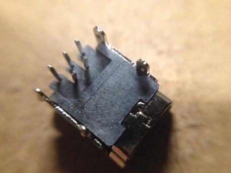
The first part to solder is the mini USB connector. This will provide power to your arduino when completed, but an RS232 / USB to Serial adapter will be needed for programming it. The mini USB socket goes in first so that you can put it in, flip the board over so that the pins are facing upwards, then put it down on the table. Before putting it in, bend the mini set of 2 pins slightly towards the front of the board so that it will fit in the holes on the PCB nicely. The weight of the PCB will hold the connector in place, and you can solder it right there.
Step 2: Pin Headers
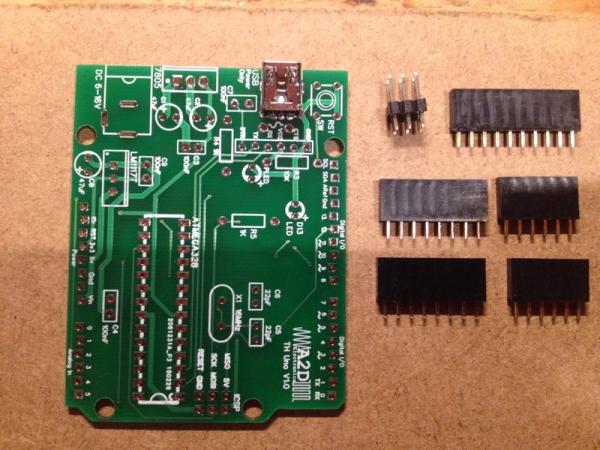
Pin headers are the next pieces to go in. You should have female headers in 6pin x2, 8pin x2, and 10pin x1. A male header of 3×2 is also required for the ICSP (In Circuit Serial Programming) header. These all go around the outside of the board, and will fit perfectly in their proper places. Solder them in with the same method as the USB socket, doing one header at a time. The headers should all be perfectly perpendicular to the PCB. To achieve this, solder only one pin of the header, then while holding the header in with your hand, melt the solder again and reposition the header to its perpendicular position. Make sure that it also sits flush against the board for the entire length. Hold it in position until the solder hardens, then continue soldering the rest of the pins.
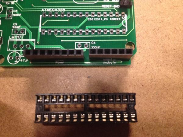
Step 3: IC Socket
Quick tip for soldering the rest of the components:
All the component leads can be placed through the board first, then bent to the side so that the components will stay in the board when flipping it over. This will make it much easier to solder as the components will hold themselves in place.
Start by placing the 28pin IC socket. Make sure to line up the divot at one end with the drawing on the PCB. This lets you know which way to insert the AtMega328P microcontroller. Even though the pins on this socket are shorter than resistors or capacitors, they can still be bent over to hold the component in place while you are soldering it.
Step 4: Resistors
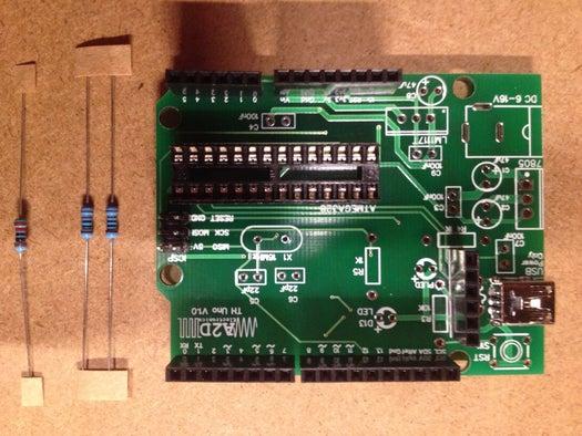
The 3 resistors can go next. It does not matter which way they are placed – resistors are not polarized. There are 2 1K ohm resistors as current-limiting resistors for the LEDs, and a 10K ohm resistors as a pull-up resistor on the reset line. 1K ohm resistors were chosen for the LED instead of the common 220 ohm ones so that the LEDs will have a lower current passing through them, thus acting more as indicators than a flashlight.
Step 5: LEDs
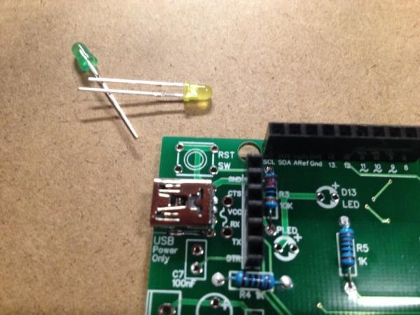
There are 2 LEDs, one as a power indicator, and the other on pin 13 of the Arduino. The longer leg on the LEDs marks the positive side (anode). Make sure to put the longer leg in the side marked + in the PCB. The negative lead of as LED is also flattened at the side, so that you can still decipher positive (anode) and negative (cathode) leads if they were cut.
Step 6: Oscillator
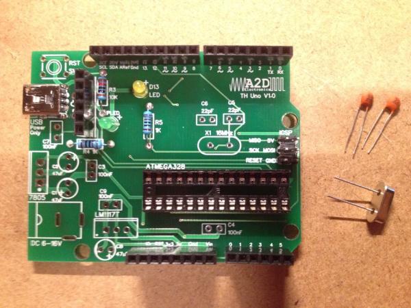
Next up is the crystal oscillator and the 2 22pF ceramic capacitors. It does not matter which way any of these get put in – ceramic capacitors and crystal oscillators are not polarized. These components will give the Arduino a 16MHz external clock signal. The arduino can produce an 8MHz internal clock, so these components are not strictly necessary, but let it operate at full speed.
Step 7: Reset Switch
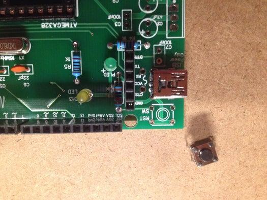
The reset switch can go next. The legs on the switch do not have to be bent, it should hold itself in the slot.
Step 8: Ceramic Capacitors
4 100nF (nano Farad) ceramic capacitors can go next. C3 and C9 help smooth out small voltage spikes on the 3.3V and 5V lines to deliver clean power to the Arduino. C7 is in series with the external reset line to allow an external device (USB to Serial Converter) to reset the Arduino at the right time in order to program it. C4 is on the Arduino’s AREF (Analog Reference) pin and GND to ensure that the Arduino measures accurate analog values on it’s analog inputs. Without C4, AREF would be considered ‘floating’ (not connect to power or ground), and will cause inaccuracies in analog readings because a floating pin will take on whatever voltage is around it, including the small AC signals in your body that have come from the wiring around you. Again, ceramic capacitors are not polarized, so it does not matter which way you put them in.
Source: Building a DIY Arduino on a PCB and Some Tips for Beginners
- What is required for programming the Arduino?
An RS232 or USB to Serial adapter is needed for programming. - How should you position pin headers during soldering?
Solder one pin first, hold the header perpendicular while melting the solder again to reposition it flush against the board. - Why were 1K ohm resistors chosen for the LEDs?
They limit current to make the LEDs act more as indicators rather than flashlights. - How do you identify the positive side of an LED?
The longer leg marks the positive side (anode), which goes into the side marked + on the PCB. - Do ceramic capacitors and crystal oscillators have polarity?
No, they are not polarized, so it does not matter which way they are placed. - What is the purpose of the 22pF ceramic capacitors?
They work with the crystal oscillator to provide a 16MHz external clock signal for full-speed operation. - Why is C4 connected to the AREF pin?
It prevents the pin from floating, which ensures accurate analog readings by avoiding interference from surrounding AC signals. - Can the AtMega328P be inserted without the socket?
The article instructs to place the 28pin IC socket first to indicate how to insert the microcontroller.