
Summary of Build the Ultimate Larson Scanner! using arduino
Summary: The author built a 16-channel Larson scanner using inexpensive 10W white LEDs, simple MOSFET-based constant-current regulators, and PWM control from a TLC5940 (Sparkfun breakout) driven by an Arduino. External current regulators protect the TLC5940 and allow high-current LEDs to be PWM'd safely. The design emphasizes through-hole parts, easy assembly, and affordable components for a large LED scanner.
Parts used in the Ultimate Larson Scanner:
- 16 10W white LEDs (Deal Extreme)
- 16 N-Channel MOSFETs (T-220 plastic case) from Digikey
- 16 0.75 Ohm 1W resistors (sense resistors) from Digikey
- 16 2n3904 transistors from Digikey
- 1 TLC5940 breakout board from Sparkfun
- 1 Arduino Pro Mini or Boarduino (Sparkfun or Adafruit)
- 16 heatsinks (surplus, sized for LEDs)
- 6 ft angle aluminum 1 1/2” x 1 1/2” (Home Depot or Lowes)
- Wire: 22 AWG for control, 18 AWG for power
- 12V power supply, at least 16A
- Stand (example 140-ENDZONE-M)
- Miscellaneous screws, nuts, and mounting hardware
- 4-40 standoffs from Digikey
I have watched the availability of high power (>10W) LED’s jump over the past year or so and… drop in price. I came across some very inexpensive 10W white LED’s from Deal Extreme that were in the $3 dollar range and put out 900lumens, which is more than a 60W incandescent bulb. I immediately thought 16 of these would make a great Larson scanner. What exact neuron sequence fired in my brain that caused this thought is unknown, but it seemed like a good idea! So as we say in Texas, “Hold my beer, I want to try something”.
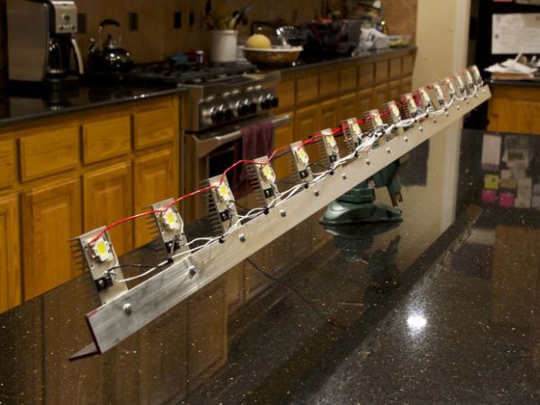
To be able to use these I needed the ability to easily regulate the current to them and to be able use a PWM signal to adjust the brightness. So I started thinking about it and doing some research. I also needed it to be simple and not require surface mount components and making circuit boards. I found some nice designs based on switching inverters but most of these were intended to be efficient constant current LED drivers with one brightness level. Or in the case of flashlight drivers, a couple of brightness levels.
Step 1: The Driver
Then I came across the classic MOSFET constant current driver for LED’s. There is a great instructable for this one here:
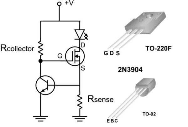
Below is my rendering of the schematic. (Original then with two mods to allow PWM)
The only thing missing was how to PWM it. I had an idea. What if instead of connecting the collector resistor to the main positive supply, I connected it to the output pin on an Arduino? If the pin was low (ground) it should turn the MOSFET off and thus the LED. After a little breadboarding I discovered that it worked great! This opened up a lot of possibilities for driving high power LED’s as the component costs for each one of these is about a dollar and they are simple to build. Instead of a breadboard. I used the old standby: Point to point.
Doing a little research on Digikey I found a great MOSFET to use. It is T-220 mount and the case is entirely plastic. This means you don’t have to worry about insulating the electrical connection to the metal tab when you mount it. And, it was less than a dollar if you buy in bulk.
Along with the 10W LED‘s from Deal Extreme, I found an 80W warm white one for $18 and a 60W RGB one for $21. That site is dangerous. 60WRGB LED’s are like crack. I ordered a couple of each and some of the plastic reflectors to go with them.
How it works (yea, the math stuff):
The heart of this current regulator is the NPN transistor. I am using the 2n3904 which has a .7V drop on the Base Emitter junction when forward biased. This voltage is also present across the Sensing Resistor Rsense. Which is also where the LED current flows to ground. Because we always have .7V here we can pick a value for this resistor that sets our LED current. To function properly the NPN transistor needs to be biased into its normal range of somewhere between 1 and 10 milliamps of current. This is where the Collector Resistor comes into play We need to size this based on the supply voltage. If it is a stand alone regulator, meaning you just want to always light the LED’s at the correct current, you should use 3.3K to 4.7K and that will work with 12VDC all the way up to 35VDC. Why would we need the different voltages? We will see when we look at the different high powered LED’s.
There are a couple versions of the constant current regulator:
The first is the classic, I just want to have my LED supplied by a constant current and not control it. Use the first circuit for that one.
Second it the “I am going to control it from and Arduino pin directly” This one also will also work for any 5volt logic gate such as the wonderful 74595 TTL shift register. There are libraries out there to drive these from an Arduino and string many of them together. This circuit will work for this application. The only real difference is that we are connecting the collector resistor to the logic output pin. If you use a 3.3K resistor the most load the gate will see is 1.5ma of current. Well within the drive capability of the TTL chip and an Arduino.
Third (and this is what I am using for my 6 foot Larson scanner!) is this one. It is the Sparkfun breakout board for the TLC5490 which conveniently has a 2.2K resistor tied to VCC on the PWM outputs. For those of you new to this chip, it features 12bit PWM and is meant to directly drive LED’s up to 100ma or servo’s. There are libraries for the Arduino to do just that. In particular there is a great one written by Alex Leone. You can find it here: This is the one I am using to drive my Larson Scanner.
Because the Sparkfun breakout board includes a 2.2 K resistor, I don’t have to include a resistor on my current regulator. How awesome is that? You have to be aware that now when the TLC5490 is “off” the 2.2K resistor turns “on” the transistor and the LED. So to turn the LED off, you have to turn on the TLC5490 output. In the code driving it you just have to think backwards sending the TLC a value of 0 turns the LED on full brightness and a value of 4095 turns it off.
I have played around with this chip for awhile and have always wanted to use it to drive larger loads. Plus running it at 100ma per output gets it very hot. Using an external current regulator for the load like this barely gets the chip warm.
Step 2: Let’s Build it!
To build the Ultimate Larson Scanner, you will need the following things:
16 10W LED’s (Deal Extreme) here
16 Constant Current Regulators consisting of:
1 N-Channel MOSFET Digikey
1 .75Ohm 1W Resistor Digikey
1 2n3904 Transistor Digikey
1 TLC5940 Breakout Board from Sparkfun
1 Arduino Pro Mini Sparkfun or Boarduino Adafruit I have used both
16 Heatsinks I got mine surplus. They need to be about the size of the ones I am using or your LED’s will overheat
6ft angle aluminum 1 1/2”X 1 1/2” Home Depot or Lowes
Wire: 22 gauge for the control connection
18 gauge for the power leads
A 12 volt power supply capable of at least 16 amp output (assuming all the LED’s are lit at once)
Stand to hold the scanner once complete This one is cheap and works great 140-ENDZONE-M
miscellaneous screws nuts etc to mount all the LED modules.
4-40 standoff’s Digikey
Tools:
Soldering tools
Drill and drill bits
4-40 tap
8-32 tap
Heat shrink tubing
tie wraps
For more detail: Build the Ultimate Larson Scanner!
- What LED drivers are used for each LED?
Each LED uses a MOSFET-based constant current regulator consisting of an N-channel MOSFET, a 0.75 ohm 1W sense resistor, and a 2n3904 transistor. - Can I PWM the LEDs from an Arduino?
Yes; connecting the collector resistor to an Arduino output pin allows that pin to PWM the MOSFET driver and control brightness. - Does the TLC5940 work with the external current regulators?
Yes; the TLC5940 breakout has 2.2K resistors on its outputs and can drive the external current regulators, but its outputs are inverted relative to LED on/off. - How do I turn LEDs fully off when using the TLC5940?
Because the TLC5940 breakout ties a 2.2K resistor to VCC, sending the maximum PWM value (4095) to the TLC5940 output turns the LED off; sending 0 turns it fully on. - Why use external current regulators with the TLC5940?
Using external regulators allows driving larger loads without heating the TLC5940, since the regulator handles the LED current. - What power supply is required?
A 12V power supply capable of at least 16A is recommended assuming all 16 LEDs may be lit simultaneously. - Are surface mount components required?
No; the design uses through-hole components to avoid surface mount assembly and custom PCBs. - What gauges of wire are recommended?
Use 22 AWG for control connections and 18 AWG for power leads. - How should the MOSFET be chosen for mounting?
Choose a T-220 mount MOSFET with a fully plastic case so the metal tab does not require insulation when mounted.
