Summary of How to Build a Soil Moisture Sensor Circuit with an Arduino
This article outlines building a soil moisture sensor using an Arduino to monitor plant hydration. It explains that the prebuilt module provides analog and digital outputs, with analog values ranging from 0 (wet) to 1023 (dry). The project connects the sensor's power and analog pins to the Arduino while leaving the digital pin unconnected to utilize precise readings.
Parts used in the Soil Moisture Sensor Project:
- Soil Moisture Sensor Module
- LED
- Arduino
In this project, we are going to build a soil moisture sensor with an Arduino microcontroller.
A soil moisture sensor, also called a hygrometer, measures the amount of moisture, or water, in the soil.
Therefore, we can tell whether the soil has enough moisture or not. So it is a good diagnostic tool for caring for plants of all types.
If the soil is extremely dry, then you will know the plant should be watered.
If the soil is very moist, then you will know that it does not need to be watered.
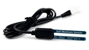
The soil moisture sensor we will build is simple to connect because we’re going to use a prebuilt module. This means everything is already included. We simply have to connect the output terminals to a microcontroller such as the Arduino.
If you type in ‘Arduino Soil Moisture Sensor’ into ebay, you will see the complete type of sensor needed to build this circuit.
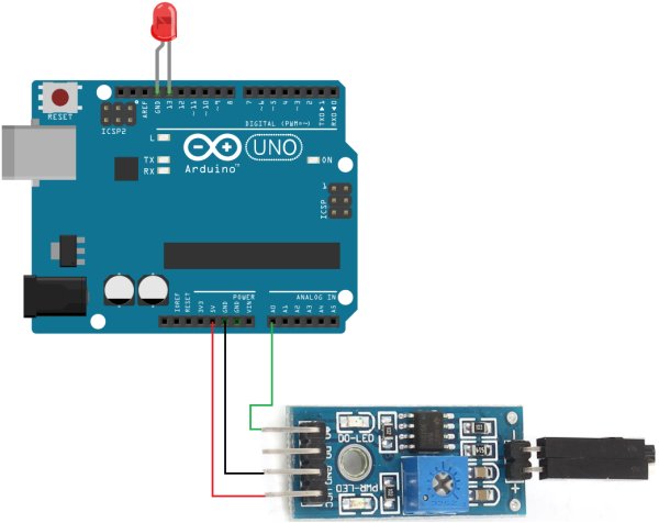
The sensor has 4 terminals for connection, Vcc (for power), GND, Analog output, and Digital output.
Vcc and ground are how the sensor gets the power it needs to operate. Here we connect 3.3V-5V of external power.
Analog output shows the value the sensor is reading which correlates to the amount of moisture it detects. The analog value varies from 0 (very wet) to 1023 (very dry). So if the soil is very dry, the analog output will have a very high reading. If the soil is we, the analog output will have a very low reading. This is how we will know whether the moisture content of the soil.
The Digital output simply goes high or low. Since we are working with a microcontroller that can interpret analog signals, this is more precise than digital signals, so we will not connect the DO pin. If we weren’t using a microcontroller, then we probably would have to use DO instead of AO.
A soil moisture sensor, again, is a very useful tool for plant care and maintenance.
Components
- Soil Moisture Sensor Module
- LED
- Arduino
The soil moisture module has 4 pins.
The table below summarizes these pin connections.
| Soil Moisture Sensor Terminals |
Arduino Terminals |
| Vcc | Connects to 5V terminal |
| GND | Connects to GND terminal |
| AO | Connects to an analog terminal (A0-A5) |
| DO | Unconnected |
Logic Probe Circuit
The logic probe circuit we will build to read logic levels is shown below.
For more detail: How to Build a Soil Moisture Sensor Circuit with an Arduino
- What is a soil moisture sensor?
A soil moisture sensor, also called a hygrometer, measures the amount of moisture or water in the soil. - How do you determine if soil needs watering?
If the soil is extremely dry, the plant should be watered, whereas very moist soil does not need watering. - What voltage range powers the sensor module?
You connect 3.3V-5V of external power to the Vcc terminal. - What analog value indicates very dry soil?
An analog output reading of 1023 indicates very dry soil. - Why is the Digital output pin left unconnected?
The Digital output pin is unconnected because the microcontroller can interpret analog signals more precisely than digital signals. - Where should the Analog output pin be connected?
The Analog output pin connects to an analog terminal on the Arduino such as A0-A5. - Can this sensor be found on eBay?
Yes, typing 'Arduino Soil Moisture Sensor' into eBay will show the complete type of sensor needed.