Summary of Build Simon Game Using Arduino
Summary: The group built a Simon game on an Arduino using 3 buttons and 4 LEDs (three for signals, one for errors). Patterns start with one random light and grow each correct round until length 7 for a win; a wrong input lights the error LED. The device is mounted on a paper plate with origami balloon diffusers. The design evolved from a binary counter project and iterated through UI, timing, and debounce fixes.
Parts used in the Simon Game:
- Arduino (microcontroller board)
- 3 push buttons
- 4 LEDs (3 signal LEDs, 1 error LED)
- Resistors for LEDs
- Resistors for button pull-downs or pull-ups
- Alligator clips (used during prototyping)
- Paper plate (body/mount)
- Origami balloons (LED diffusers)
- Wires/jumper cables
High Level Description:
For part 3 of the lab, our group decided to build a “Simon” game. Our game setup uses 3 buttons and 4 LEDs. Each button corresponds to one LED and the 4th LED is used to indicate an error. The game starts with the Arduino flashing one of the 3 lights, chosen randomly. The user must then press the button corresponding to that light. If the user’s input is correct, the Arduino extends the pattern by one and the user must then match that extended pattern. If the user’s input is incorrect, the error light goes off and the user loses the game. This process repeats until the pattern reaches length 7, in which case the user wins the game.
Our game is mounted a paper plate for support and uses origami balloons to diffuse light from the leds.
Here is a video of the game in action:
High Level Design Process:
We began with brainstorming. Our initial ideas included interactive and non-interactive designs. These ideas included pre-set light display patterns (Morse code or musical patterns), diffusers using various translucent paper and plastic covers, and a binary counter.
We decided to first make the binary counter, as we thought it would be both technically and visually interesting. We also would have the opportunity to use our origami balloon/lantern diffusers which we thought were pretty cool.
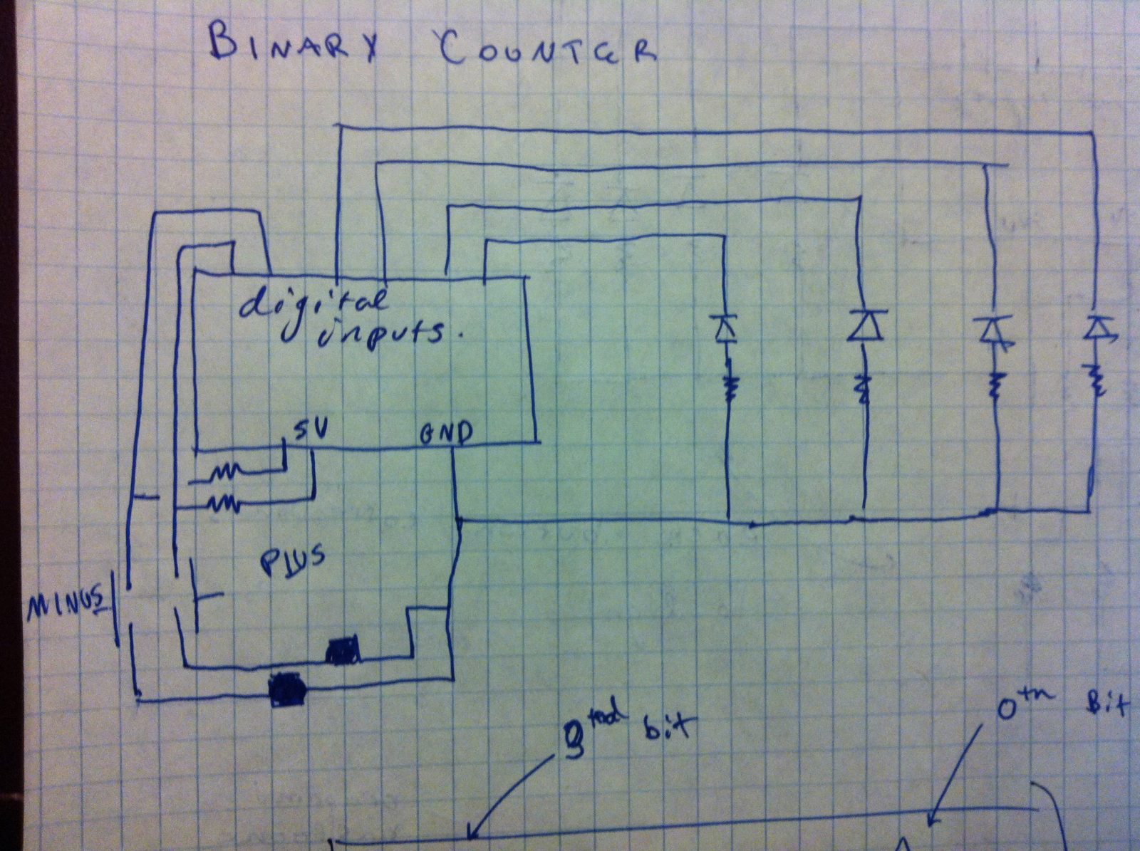
The binary counter consisted of two buttons (an increment and a decrement) as well four LEDs to display a 4 bit number. With those four LEDs, we could count from 0 to fifteen, and display a fun pattern on overflow or underflow.
We began by sketching our design and drawing the circuitry. Here are our initial brainstorming sketches:
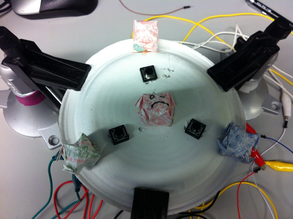
We then assembled our circuit and wrote the code to power our binary counter (technical details given below). In the end we built this:
After completing the binary counter though, we considered our design choices and thought about what we could do to make our circuit better. After making modifications and iterating through different design choices, we decided that what our circuit was lacking was an interesting method of interacting with the counter. We liked how the binary counter was interactive; however, it was limited to single presses doing the same thing every time. With this in mind, we considered various ways of expanding on our counter, such as using the counter to select and play one of 16 different pre-set light patterns (which could be Morse code messages or other interesting displays) or to play a game. In the end we decided to create the Simon game described above.
Initial design decisions for Simon included how to organize the user interface and how many lights and buttons to include. We decided to use a paper plate as the body of our game as it was easy to manipulate but also gave sufficient support. We initially planned to make the game with 4 lights and 4 buttons, but reduced those numbers to 3 as we continued in the design process and faced limitations due to the availability of resources and bulkiness of alligator clips.
Once the basic layout of the game was implemented, we made gameplay decisions like how long to wait between flashes of light and how long the pattern should be for the user to win. We made these decisions by playing the game ourselves, and by having other people play our game. We also had to work out bugs such as a single button press being registered twice. After trying our game with different parameters, we arrived at our final design.
Technical Documentation / Technical Design Choices:
There were 2 main circuit components that we used to power our game: LEDs and buttons (these were used with resistors, as needed). In the first 2 parts of the lab, we became familiar with using LEDs. Helpful information about using LEDs with Arduinos is found at http://arduino.cc/en/Tutorial/blink.
LEDs are implemented by creating a connection between an Arduino pin and ground. (Image from arduino.cc/en/tutorial/blink)
We then looked up how to use buttons with Arduino at http://arduino.cc/en/tutorial/button. To use a button, we needed to provide a path from ground to 5v (with a resistor) as well as a path to an input pin to sense when the button is closed.
For more detail: Simon Game Using Arduino
- How many buttons and LEDs does the Simon game use?
The game uses 3 buttons and 4 LEDs (three for signals and one for errors). - What indicates an incorrect user input?
The fourth LED is used to indicate an error when the user inputs incorrectly. - How does a player win the game?
The player wins when the pattern reaches length 7 and they successfully reproduce it. - What was the project originally before becoming Simon?
The project began as a binary counter using two buttons and four LEDs. - What materials were used to diffuse the LED light?
Origami balloons were used to diffuse the light from the LEDs. - Why was the design reduced to 3 buttons and 3 signal LEDs?
The design was reduced due to limited resources and the bulkiness of alligator clips during prototyping. - What physical support holds the game components?
The game is mounted on a paper plate for support. - How were timing and pattern length decisions made?
Timing and pattern length were decided by playtesting the game with the creators and other people. - What common Arduino tutorials were referenced?
The group referenced Arduino tutorials for blink (LED usage) and button usage on the Arduino website. - How was the double-registration of button presses addressed?
They debugged the issue (debouncing) by testing different parameters and fixing the bug during iteration.