
Summary of BLUE_P: Wireless Arduino Programming Shield
This article details a DIY project to create a wireless Arduino programming shield using an HC-05 Bluetooth module, eliminating the need for USB cables. The guide covers configuring the module via AT commands, wiring connections between the Arduino and Bluetooth module, implementing a voltage divider for signal compatibility, and uploading code through a PC's Bluetooth COM port.
Parts used in the Wireless Arduino Programming Shield:
- Arduino board
- Bluetooth module HC-05
- USB cable
- PC
- Dotted PCB
- Male female connectors
- Resistors
- Capacitor
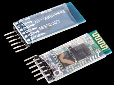
Many times we make projects using Arduino, while working with it we need to connect it with PC to upload program using USB cable. In this tutorial, I’m going to replace this USB cable with a wireless programming shield. This shield is build using a Bluetooth module HC-05.
Program Arduino boards without using traditional USB cables.
By using cheap Bluetooth module HC-05 you can Program the Arduino boards wirelessly.
For making this module capable to upload program, change some parameters such as name, role, baud rate, etc. by using AT commands. To change these parameters connect HC-05 with Arduino as shown in diagram 1.
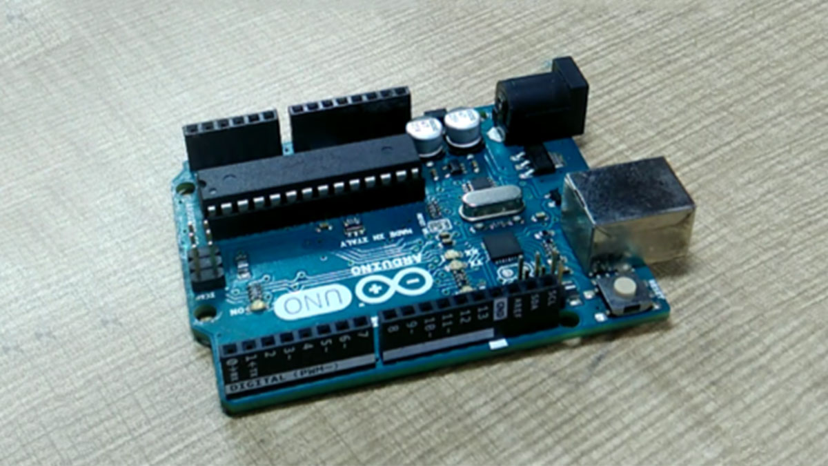
VCC of HC-05 to 5volt of Arduino, Ground to the ground, Tx to the digital pin 10 and Rx to the digital pin 11 of Arduino.
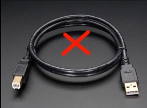
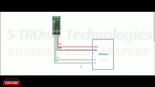
Connect this board with pc using USB cable. And upload code.
Program 1
#include
SoftwareSerial BTSerial(10, 11); // RX | TX
void setup()
{
pinMode(9, OUTPUT); // this pin will pull the HC-05 pin 34 (key pin) HIGH to switch module to AT mode
digitalWrite(9, HIGH);
Serial.begin(9600);
Serial.println(“Enter AT commands:”);
BTSerial.begin(38400); // HC-05 default speed in AT command more
}
void loop()
{
// Keep reading from HC-05 and send to Arduino Serial Monitor
if (BTSerial.available())
Serial.write(BTSerial.read());
// Keep reading from Arduino Serial Monitor and send to HC-05
if (Serial.available())
BTSerial.write(Serial.read());
}
For enter the HC-05 into AT command mode press key on it before connecting the VCC of HC-05 to the 5volt of Arduino.
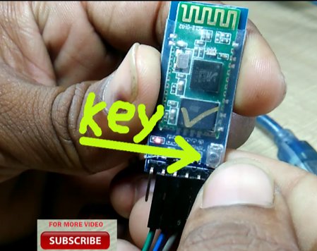
If your module not have this key, don’t get panic. There are some breakout boards without this key, but if you see the pinout of them, you will find a special pin on it with notation key.
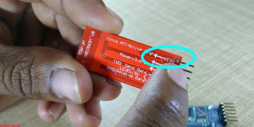
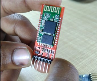
So for enter such modules in AT command mode connect Key pin to the 3.3volt pin of Arduino before connecting the VCC to the 5volt pin. LED on this module blinks slowly, once in every 2 seconds, this indicate that the HC-05 is in AT command mode.
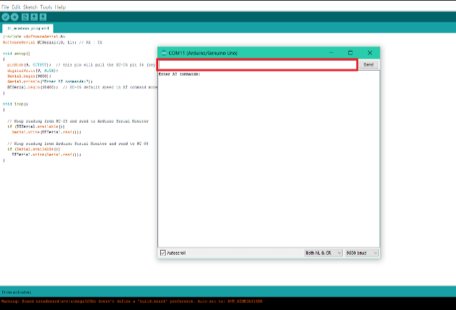
Open the serial monitor it saying that enter AT commands, type AT in send box which is highlighted by red color in picture, and hit enter or click on send button, it replies ok, in case if it replies with some error don’t get panic check connections and try again. Enter all commands by correct sequence.
Remove all connections and make new connections like diagram2. Tx of Arduino to the Rx of HC-05 and vice versa, Vcc of Bluetooth module to the 5Volt of Arduino, and ground to the ground.
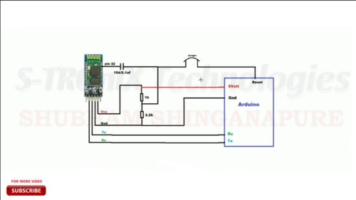
While burning program to the microcontroller, it should be in reset state, In Arduino Uno board there is ATMEGA328p microcontroller, and according to its datasheet it gets reset when Low logic signal applied to its reset pin. So to apply this low signal to reset pin of Arduino, I using POI9 (Programmable Input/ Output), pin 32 of HC-05, connect it to the reset pin of Arduino. While making this connection we need to remember one thing that is, different signal level of both boards, as Bluetooth module support 3.3volt signal level and Arduino has 5 volt. So to maintain 3.3 volt on pin 32 of HC-05 we need to place a voltage divider circuit there as shown in diagram 2.
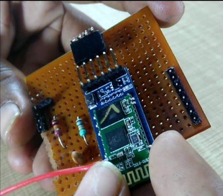
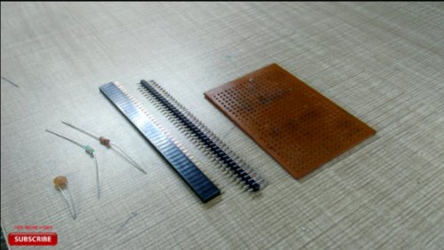
Using doted PCB, some male female connectors, resistors and a capacitor, I make the board like an Arduino shield, so can easily mount it on Arduino board.
After soldering all components it’s looking like this
Now connect the Bluetooth module with your pc, go to Bluetooth setting of your PC and select your device from list of available devices, as I rename this module it showing me BLUE_P click on it, it will ask for password type 1234 which is default password of HC-05 and click next.
After connecting PC with HC-05, the status led on it will blink in every one second. Now check on which com port it gets connected. For that click on more Bluetooth option, new window will open, click on com ports, you will fine two COM ports allocated for BLUE_P i.e. HC-05, one is incoming and other is outgoing. Remember the outgoing port number.
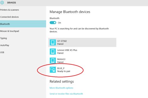
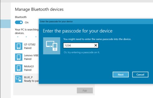
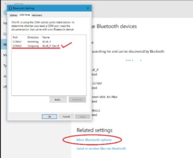
Let’s upload the program to Arduino over this Bluetooth Arduino programming shield. Open the blink program from the examples, select COM port from tool menu which allocated for Bluetooth outgoing, and click upload button. Program gets uploaded. Here I make and test this wireless Arduino programming shield successfully. And you also can make this shield easily by following these steps.
For more, watch my video on this topic here’s the link. And if you like it gives a thumbs up, comment down your doubts, and for more updates stay connected.
Download source code & diagram: click here
Read More Detail:BLUE_P: Wireless Arduino Programming Shield
- How can I program Arduino boards without using traditional USB cables?
You can use a cheap Bluetooth module HC-05 to upload programs wirelessly by changing specific parameters using AT commands. - What pins should I connect on the HC-05 to the Arduino for configuration?
Connect VCC to 5volt, Ground to ground, Tx to digital pin 10, and Rx to digital pin 11 of the Arduino. - How do I enter the HC-05 into AT command mode if it has no physical key?
Connect the Key pin to the 3.3volt pin of the Arduino before connecting the VCC to the 5volt pin until the LED blinks slowly. - What is the default password required to connect the HC-05 to a PC?
The default password for the HC-05 module is 1234 when prompted during the Bluetooth pairing process. - Why is a voltage divider circuit necessary in this project?
A voltage divider is needed to maintain a 3.3 volt signal level on the HC-05 reset pin because the Arduino operates at 5 volts. - Which COM port should I select in the Arduino IDE to upload the program?
Select the outgoing COM port allocated for the Bluetooth device from the tool menu in the Arduino IDE. - Does the HC-05 module support 5 volt signals directly?
No, the Bluetooth module supports only a 3.3 volt signal level, requiring a voltage divider for the reset connection. - What indicates that the HC-05 is successfully in AT command mode?
The LED on the module blinks slowly, once every 2 seconds, indicating it is in AT command mode.
