Summary of BLACKBOARD V-PLOTTER
This article details the construction of a Vertical Blackboard V-Plotter, a CNC machine designed to draw text and images on vertical surfaces using stepper motors, gravity, and counterweights. The project utilizes an Arduino Mega 2560 with RAMPS 1.4 and Makelangelo firmware to control two stepper motors and a servo for pen lifting. Key assembly steps include mounting motors on the board, building a balanced pen holder with a plastic coil and cable glands, and configuring the firmware for polargraph kinematics.
Parts used in the Vertical Blackboard V-Plotter:
- Arduino Mega 2560
- RAMPS 1.4 Controller
- A4988 Stepper Driver Module (2pcs)
- NEMA 17 Stepper Motor (2pcs)
- SG90 Servo Motor
- Blackboard (780x1200mm)
- GT2 6mm Timing Belt (2000mm)
- GT2 Timing Pulley 80 Teeth (2pcs)
- XH2.54mm – 4P 20cm Wire Cable Double Connector (2pcs)
- 8P Rainbow Ribbon Cable (2 meter)
- Two cores Power Cable (2 meter)
- PVC Square Plastic Electrical Conduit (1 meter)
- Empty Plastic Coil Spool
- Cable Gland For 8 - 12mm Cable Diameter (2pcs)
- Round Neodymium Magnets 10mm x 2mm (16pcs)
- Power Supply 12/24 VDC
- Arduino programming cable (1.8m)
- M10 Nuts
- Cable ties
- A1 size paper
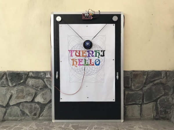
In this instructable, I’d like to share how to build a vertical plotter that can draw texts and images on the blackboard.
Let’s getting started.
Time-lapse video with hatch fill extension from Inkscape.
Step 1: Bill of Materials
Main components:
- 1pcs x Arduino Mega 2560.
- 1pcs x RAMPS 1.4 Controller.
- 2pcs x A4988 Stepper Driver Module.
- 2pcs x Stepper Motor NEMA 17.
- 1pcs x Servo Motor SG90.
- 1pcs x Blackboard Dimension 780x1200mm.
- 1pcs x GT2 6mm Timing Belt 2000mm.
- 2pcs x GT2 Timing Pulley 80 Teeth.
- 2pcs x XH2.54mm – 4P 20cm Wire Cable Double Connector.
- 2 meter x 8P Rainbow Ribbon Cable.
- 2 meter x Two cores Power Cable.
- 1 meter x PVC Square Plastic Electrical Conduit.
- 1pcs x Empty Plastic Coil Spool. I reuse empty plastic coils that is used to coil the soldering tin wires.
- 2pcs x Cable Gland For 8 – 12mm Cable Diameter.
- 16pcs x Round Neodymium Magnets 10mm x 2mm.
- 1pcs x Power Supply 12/24 VDC.
- 1pcs x Arduino programming cable with length 1.8m.
- Some nut M10, cable ties, paper A1 size.
Step 2: Ideas
Blackboard V-Plotter is a kind of CNC plotter that draws texts and pictures by moving a pen on a vertical surface. It has a simple mechanical structure, including:
- One blackboard.
- Two stepper motors with pulleys and belts.
- One pen lifting micro servo.
- Couple of counterweights.
- And gravity force.
I have an 780 x 1200mm blackboard that my kids no longer use, so I make use of it to build a vertical plotter. My vertical plotter configuration is described in the picture below.
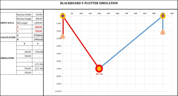
- Machine Width: 550mm.
- Machine Height: 800mm.
- Belt Length: 1000mm.
Step 3: Blackboard Assembly
- Preparing a blackboard, my blackboard has outer dimension 780 x 1200 mm including aluminum support width 30mm.
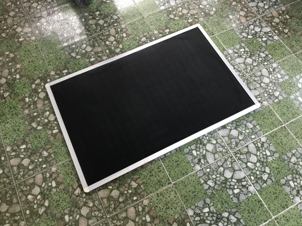
- Drilling 2 holes for mounting 2 stepper motors, the distance between two hole centers is 600mm.
- Mounting 2 stepper motors at the backside of blackboard.
- Attaching 2 pcs x pulleys 80 teeth to the motor shafts at the blackboard frontside. Pulley GT2 80 teeth has a pitch of 2mm per tooth so its diameter is: 80×2/PI = 50.955mm.
- Drilling 4 holes to mount Arduino Mega 2560 + RAMPS 1.4 board at the blackboard top center.
Step 4: Pen Holder Assembly
The main components to build the pen holder are including as follow:
- Flow coupler, including dust cap.
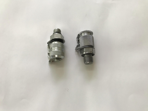
- Empty tin wire plastic coil with center hole diameter 19mm, height 23mm and outer diameter 55mm.
- GT2 6mm timing belt 2000mm and two cable gland for 8 – 12mm dia. cable. I used 2 type of cable glands, one is made from plastic, the other from metal.
Firstly, I cut 2m timing belt into two segments, each 1m length. To hang the pen holder, I removed the chains from flow coupling and connected them to 2 timing belts by cable ties.
Two cable glands were inserted into center hole of empty plastic coil. I drilled 8 holes and installed 4 bolts M3x50 symmetrically along the plastic coil to hang the timing belts. Later we can use these bolts to hang additional counterweights if needed.
I glued a servo at bottom of plastic coil (at metal cable gland side) and soldered 3 wires from servo to RAMPS 1.4 controller. Finally, pen holder was hung on the motor stepper pulleys. I moved it manually and checked if it slipped or not.
Update: The pen holder was shaked and vibrated during plotting so I had to did some adjustments to get its balancing. The steps are as follows:
- Adding some more counterweights – nuts M10.
- Connecting the tin wire plastic coil with a round plastic, 100mm in diameter, thickness 10mm.
- Glueing the micro servo into round plastic and adjusting the servo arm so that it is as close to the pen tip as possible.
- Attaching the pen, tightening a cable gland to clamp it and try lifting and lowering the pen by rotating servo arm.
- Done. And it worked much better.
Step 5: Connection
1. Schematic
The V-Plotter connection diagram is shown below:
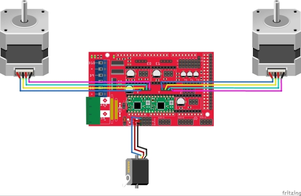
The main controllers of vertical plotter are an Arduino Mega 2560 and RAMPS 1.4. They control 2 stepper motors via A4988 drivers and one servo motor.
Notes:
- In order for vplotter to function properly, two stepper motors should rotate in opposite directions so I had to reverse the wires of right side motor.
- The RAMPS 1.4 provides four servo male headers tied to pins D11, D6, D5 & D4. My pen lift micro servo is controlled by pin D11.
- Regarding power supply for servo, I connected Vcc and 5V pins together (using jumper, 5V & Vcc headers for servo power supply are located nearby RESET button) following to the instructions from this page: https://reprap.org/wiki/RAMPS_1.4
“The 5V pin in that connector on RAMPS only supplies the 5V to the auxiliary servo connectors. It is designed so that you can jumper it to the VCC pin and use the Arduino’s power supply to supply 5V for extra servos if you are only powered from USB or 5V. Since there is not a lot of extra power from the Arduino’s power supply you can connect it directly to your 5V power supply if you have one. You can also leave this pin not connected if you have no plan to add extra servos“.
2. V-Plotter connection
- Hanging this pen holder on 2 pulleys of stepper motors, connecting all wires. For programming cable, I used an HP printer cable with length about 1.8m (HP Original 8121-0868 USB 2.0 A to B A-B Printer Cable) and it was pre-threaded inside the square plastic conduit.
- To arrange the cables neatly and aesthetically, I used a PVC square plastic electrical conduit to run the wiring inside. In addition, eight neodymium magnets were glued on the blackboard backside according to the A1 paper size.
- Covering plastic conduit. Done.
- Preparing an A1 paper for testing.
Step 6: V-Plotter Firmware
I used Makelangelo firmware at this GitHub, which was created and developed by Dan Royer – Marginally Clever Robots, Limited. Makelangelo firmware can be used in many different controllers and kinematic systems.
- Robot styles supported
#define POLARGRAPH       1  // polargraph like Makelangelo
#define TRADITIONALXY    3  // gantry 3 axis setup.
#define COREXY           2  // gantry CoreXY setup.
#define ZARPLOTTER       4  // 4 motor, x-shaped 2D motion
#define SKYCAM           5  // 4 motor, x-shaped 3D motion
#define DELTA            6  // 3 arm delta robot, rotary action.  untested.
#define STEWART          7  // 6 arm stewart platform, rotary action.  untested.
#define ARM3             8  // 3DOF palletizing robot arm.
#define SIXI             9  // 6DOF robot arm.
#define TRADITIONAL6    10  // 6 axis machine, no restrictions.
#define SCARA           11  // 2 axis SCARA.<br>
- Microcontrollers supported
#define BOARD_RUMBA        1  // Reprap discount Rumba board
#define BOARD_RAMPS        2  // Mega2560 + Ramps 1.4
#define BOARD_SANGUINOLULU 3  // Sanguinolulu
#define BOARD_TEENSYLU     4  // Teensylu
#define BOARD_WEMOS        5  // Wemos D1 R2 + CNC Shield v3 (see board_wemos.h)
#define BOARD_SIXI_MEGA    6  // Arduino Mega + custom shield for Sixi 2 robot
#define BOARD_CNCV3        7  // Mega2560 + CNC Shield v3
#define BOARD_ESP32        8  // ESP32 + Marginally Clever Polargraph PCB.
Step 7: Firmware Adjustment
I have made a few adjustments on Mekalangelo firmware to make it compatible with my plotter. Details are as follows:
- “configure.h“: Configuration settings for vertical plotter
– Plotter type: Polargraph
– Controller: Arduino Mega 2560 + RAMPS 1.4
– No LCD
//------------------------------------------------------------------------------
// Robot styles supported
//------------------------------------------------------------------------------
#define MACHINE_STYLE POLARGRAPH

//------------------------------------------------------------------------------
// LCD panels supported
//------------------------------------------------------------------------------
#define LCD_TYPE LCD_NONE

//------------------------------------------------------------------------------
// Microcontrollers supported
//------------------------------------------------------------------------------
#define MOTHERBOARD BOARD_RAMPS
- “robot_polargraph.h“: Configuration settings for polargraph
– Version: MAKELANGELO_5
– With Pen Lift.
– No LCD – No SDCard – No limit switches.
#define MACHINE_HARDWARE_VERSION   MAKELANGELO_5  // Change me
#define MACHINE_HAS_LIFTABLE_PEN
.................................................
#if MACHINE_HARDWARE_VERSION == MAKELANGELO_5
#ifndef MAX_SEGMENTS
#define MAX_SEGMENTS         (32)
#endif
//#define USE_LIMIT_SWITCH
//#define HAS_SD
//#define HAS_LCD
#endif
- “configMotors.h“: Stepper motor and pulley settings
– I used stepper motors NEMA 17 with step angel: 1.8°. So the number of steps required for stepper motors to make 1 complete revolution: 200 step/rev.
– A4988 micro-steps setting: 16.
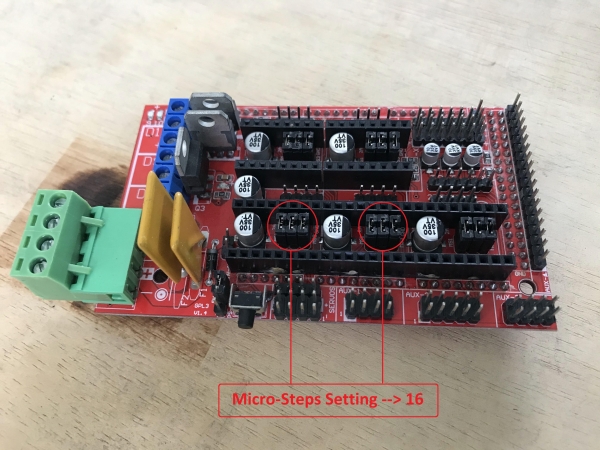
– I used GT2 timing belt, which has a pitch of 2mm per tooth and GT2-80 pulleys which have 80 teeth. The value 80×2=160mm (PULLEY_PITCH) means the circumference of pulleys (pulley diameter = 160/PI = 50.9mm) or the travel distance of timing belts when stepper motors make 1 revolution.
#pragma once
/*
 * Motor settings shared between various kinematic systems
 */
// choose one of the following
#define NORMAL_MOTOR_STEPS   200  // 1.8 degrees per step

// stepper motor drivers can use microstepping to split steps into fractions of steps for greater precision.
// A4988 drivers (Marginallyclever.com default) use 16x.

#ifndef MICROSTEPS
#define MICROSTEPS           (16.0)
#endif

// Using GT2 timing belt, which has 2mm teeth.
// I also use GT2-80 pulleys which have 80 teeth.
// 80*2 means the pitch is 160.

#define PULLEY_PITCH         (160.0)

#if NORMAL_MOTOR_STEPS == 200
#define DEFAULT_FEEDRATE     (180.0)
#define DEFAULT_ACCELERATION (150.0)
#define DEGREES_PER_STEP     (1.8)
#endif
#if NORMAL_MOTOR_STEPS == 400
#define DEFAULT_FEEDRATE     (100.0)
#define DEFAULT_ACCELERATION (150.0)
#define DEGREES_PER_STEP     (0.9)
#endif
- “board_ramps.h“: Arduino Mega 2560 pin setting
Take note that the RAMPS 1.4 provides four servo male headers tied to pins D11, D6, D5 & D4. I used pin D11 for controlling pen lift micro servo.
#define MAX_BOARD_SERVOS          (1)   /* Default: 4 */
#define SERVO0_PIN                (11)   /* Default: 11 - Servo 1 */
#define SERVO1_PIN                (6)
#define SERVO2_PIN                (5)
#define SERVO3_PIN                (4)
Source: BLACKBOARD V-PLOTTER
- How is the pen lifted?
The pen is lifted by a micro servo motor glued to the bottom of the pen holder's plastic coil. - What firmware is used for this plotter?
The project uses Makelangelo firmware developed by Dan Royer from Marginally Clever Robots. - How are the stepper motors configured?
The two stepper motors must rotate in opposite directions, requiring the wires of the right side motor to be reversed. - Which pin controls the pen lift servo?
The pen lift micro servo is controlled by pin D11 on the RAMPS 1.4 controller. - What is the pulley pitch value used in the code?
The PULLEY_PITCH is set to 160.0 based on 80 teeth multiplied by the 2mm GT2 belt pitch. - How was the pen holder vibration issue solved?
Vibration was reduced by adding M10 nuts as counterweights and gluing the servo into a round plastic disc. - What type of motors are used for the main drive?
The plotter uses NEMA 17 stepper motors with a step angle of 1.8 degrees. - How are the cables organized aesthetically?
Cables are run inside a PVC square plastic electrical conduit to keep them neat.