Summary of Arduino Sketch Event Loop Demo
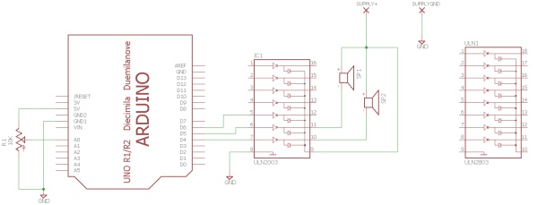
This Arduino sketch demonstrates an event-loop programming technique to generate two simultaneous square waves at different frequencies on digital pins 4 and 5. By using `micros()` for non-blocking timing, the code executes parallel tasks without delays. The project serves as a foundation for students to later integrate an analog potentiometer to modulate the wave pitches dynamically.
Parts used in the Event Loop Demo:
- Arduino Board
- Digital Output Pin 4
- Digital Output Pin 5
- Analog Potentiometer (for future extension)
This sketch is used by Exercise: Event-Loop Programming.
Full Source Code
The full code is all in one file EventLoopDemo.ino.
// EventLoopDemo.ino : demonstrate generation of two simultaneous square waves at different rates

// The example program generates audio-frequency square waves at different
// pitches on pins 4 and 5 to demonstrate a simple event-loop control structure
// allowing parallel execution of two timed tasks.  The exercise asks the
// student to add an analog potentiometer input and use the input value to
// modulate the pitch by varying the waveform timing.

// Define the pin numbers on which the outputs are generated.
const int outputPin1 = 4;
const int outputPin2 = 5;

/****************************************************************/
// This function is called once after reset to initialize the program.
void setup()
{
  // Initialize the digital output pins to output drive mode.
  pinMode( outputPin1, OUTPUT );
  pinMode( outputPin2, OUTPUT );
}

/****************************************************************/
// Global variables.
long next_output_time_1 = 0;        // timestamp in microseconds for when next to update output 1
long next_output_time_2 = 0;        // timestamp in microseconds for when next to update output 2

long output_interval_1 = 500;       // interval in microseconds between output 1 updates
long output_interval_2 = 700;       // interval in microseconds between output 2 updates

int output_state_1 = LOW;           // current state of output 1
int output_state_2 = LOW;           // current state of output 2

/****************************************************************/
// This function is called repeatedly as fast as possible from within the
// built-in library to poll program events.

void loop()
{
  // read the current time in microseconds
  long now = micros();

  // Polled task 1 for output 1.  Check if the next_output_time_1 timestamp has
  // been reached; if so then update the output 1 state.
  if (now > next_output_time_1) {

    // reset the timer for the next polling point
    next_output_time_1 = now + output_interval_1;

    // toggle the output_state_1 variable
    output_state_1 = !output_state_1;

    // update output pin 1 with the new value
    digitalWrite( outputPin1, output_state_1 );
  }

  // Polled task 2 for output 2.  Check if the next_output_time_2 timestamp has
  // been reached; if so then update the output 2 state.
  if (now > next_output_time_2) {

    // reset the timer for the next polling point
    next_output_time_2 = now + output_interval_2;

    // toggle the output_state_2 variable
    output_state_2 = !output_state_2;

    // update output pin 2 with the new value
    digitalWrite( outputPin2, output_state_2 );
  }
}
/****************************************************************/
Source: Arduino Sketch Event Loop Demo
- What is the primary purpose of this sketch?
To demonstrate generation of two simultaneous square waves at different rates using an event-loop control structure. - Which pins are used to generate the output signals?
The outputs are generated on digital pins 4 and 5. - How does the code handle parallel execution of tasks?
It uses a simple event-loop structure that polls timestamps based on micros() to update outputs independently. - What variables store the timing intervals for the outputs?
The variables output_interval_1 and output_interval_2 store the intervals in microseconds. - Can the pitch of the waves be modified according to the text?
Yes, the exercise asks students to add an analog potentiometer input to modulate the pitch by varying waveform timing. - What function initializes the program after reset?
The setup function initializes the digital output pins to output drive mode. - How often does the loop check for task updates?
The loop checks repeatedly as fast as possible from within the built-in library. - What data type is used for the timestamp variables?
The long data type is used for next_output_time_1 and next_output_time_2.