Summary of Bike Speedometer using an Arduino
This article details a DIY Arduino-based bike speedometer that uses a magnetic reed switch and magnet to detect wheel rotations. The system calculates speed in mph and displays it on an LCD screen mounted on the handlebars. Users can calibrate the device for any wheel by entering the radius into the firmware. The project involves soldering components onto a protoboard, mounting the sensor on the wheel spokes and frame, and connecting power via a 9V battery.
Parts used in the Bike Speedometer:
- Arduino Uno REV 3
- Magnetic Reed Switch
- 10K Ohm Carbon Film Resistor
- 9V Alkaline Battery
- Heavy-Duty 9V Snap Connectors
- PC Board with Copper
- Parallax Serial Backlit LCD
- SPST PC-Mountable Submini Toggle Switches
- Male Header Pins
- Female Pin Sockets
- 22 Gauge Wire
- Solder
- Sand paper
- Plywood
- Wood glue
- Hot glue
- Screws
- Zip ties
- Sugru
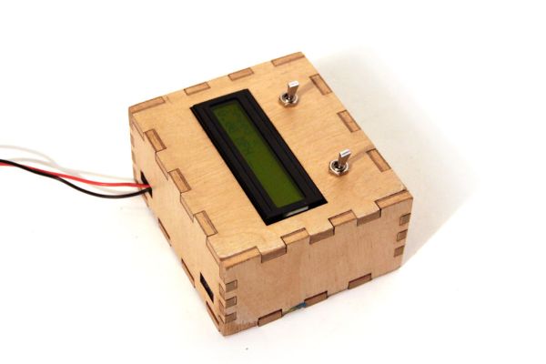
Monitor your road speed using the Arduino. This project uses a magnetic switch (also called a reed switch) to measure the speed of one of the bike’s wheels. The Arduino calculates the mph, and send this information out to the LCD screen on the handlebars as you ride. It is compatible with any kind of bike/wheel, simply enter the radius of the wheel in the firmware to calibrate the device for your setup.
Parts List:
(1x) Arduino Uno REV 3 Radioshack 276-128
(1x) Switch-Magnetic Reed Radioshack 55050593
(1x) 10K Ohm 1/4-Watt Carbon Film Resistor Radioshack #271-1335
(1x) 9V Alkaline Battery Radioshack #23-866
(1x) Heavy-Duty 9V Snap Connectors Radioshack #270-324
(1x) PC Board with Copper Radioshack #276-147
(1x) Parallax 27977-RT Serial Backlit LCD Radioshack 276-120
(x2) SPST PC-Mountable Submini Toggle Switch Radioshack #275-645
(2x) Male Header Pins Jameco 103393
(1x) Female Pin Sockets Jameco 308567
Additional Materials:
22 Gauge Wire Radioshack #278-1224
Solder Radioshack #64-013
sand paper
plywood
wood glue
hot glue
screws
zip ties
sugru
Download Arduino IDE
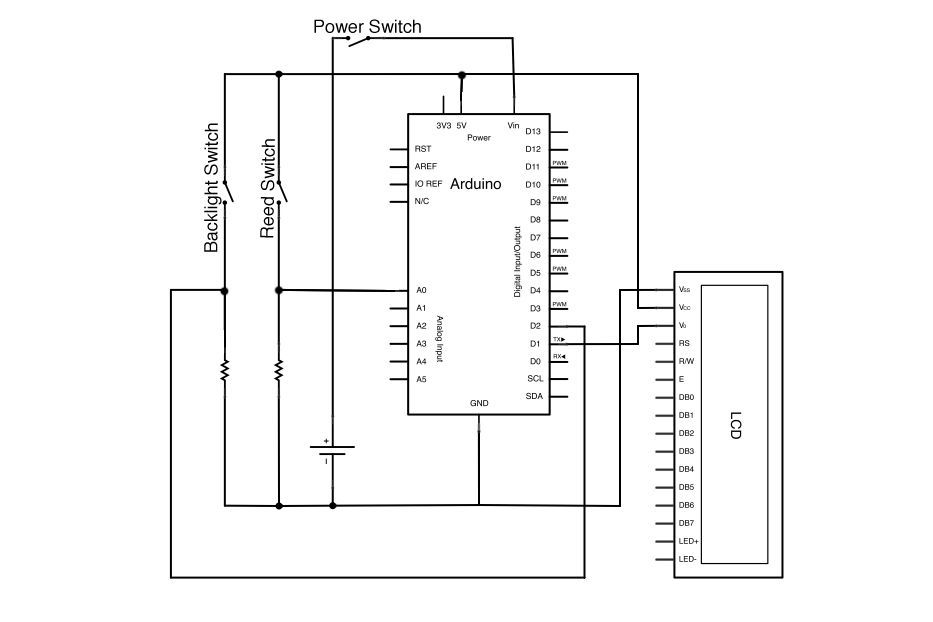
Step 1: Schematic
The schematic for this project is shown above.
It consists of three switches:
-one to connect to a 9V power supply
-one to switch the backlight of the LCD on and off
-a magnetic switch (called a reed switch) which closes each time the wheel completes one full rotation.
The Parallex LCD is designed to connect to the Arduino using only three pins (ignore the labels and the other pins int his schematic). One to 5V, one to ground, and a third to serial out (TX)- on the Arduino, serial out is digital pin 1.
10kOhm resistors are connected to the reed and backlight switches to prevent excess current between 5V and ground (you should never directly connect 5V and ground on the Arduino!)
Step 2: Protoboard
Solder three rows of header pins on the protoboard so that the Arduino will snap to it as shown in the images above.
Step 3: Reed Switch
The reed switch is comprised of two pieces, a switch and a magnet. The switch has two wires extending out from it, when a magnet comes near the switch it causes a small mechanical piece to move and close the switch momentarily.
Solder a 10kOhm (current limiting) resistor between A0 and ground on the protoboard. Connect long pieces of stranded wire to A0 and 5V- these wires will wrap around the bike and attach to the reed switch.
Step 4: Mount Reed Switch on Wheel
Secure both the magnet and reed switch to your bike wheel with electrical tape (either wheel is fine). As shown in the images above, the magnet connects to one of the tire spokes and the reed switch connects to the frame of the bike. This way, each time the bike wheel turns the magnet moves past the switch. Connect the leads form the reed switch to the long wires from your protoboard (orientation does not matter here- it’s just a switch)
Use the code below to test your reed switch. When the magnet on the wheel moves past the switch, the arduino should print ~1023, otherwise it will print ~0. Open the serial monitor (Tools>>Serial Monitor) in Arduino IDE to test for your own setup. If the magnet does not seem to be affecting the reed switch, try repositioning it or even adding a stronger magnet if you have one.
(1x) Switch-Magnetic Reed Radioshack 55050593
(1x) 10K Ohm 1/4-Watt Carbon Film Resistor Radioshack #271-1335
(1x) 9V Alkaline Battery Radioshack #23-866
(1x) Heavy-Duty 9V Snap Connectors Radioshack #270-324
(1x) PC Board with Copper Radioshack #276-147
(1x) Parallax 27977-RT Serial Backlit LCD Radioshack 276-120
(x2) SPST PC-Mountable Submini Toggle Switch Radioshack #275-645
(2x) Male Header Pins Jameco 103393
(1x) Female Pin Sockets Jameco 308567
For more detail: Bike Speedometer using an Arduino
- How does the project measure road speed?
The project uses a magnetic reed switch to detect when a magnet on the wheel passes, allowing the Arduino to calculate miles per hour. - Can this device be used with any type of bike or wheel?
Yes, it is compatible with any kind of bike or wheel as long as you enter the specific radius of the wheel in the firmware. - What is the function of the 10kOhm resistors in the schematic?
The resistors are connected to prevent excess current between 5V and ground, which could damage the Arduino. - Which pins should be used to connect the Parallax LCD to the Arduino?
The LCD connects using only three pins: one to 5V, one to ground, and a third to serial out (digital pin 1). - Where should the magnet and reed switch be mounted on the bike?
The magnet connects to a tire spoke while the reed switch connects to the bike frame so they pass each other during rotation. - How do you test if the reed switch is working correctly?
You open the Serial Monitor in Arduino IDE; the output should print approximately 1023 when the magnet passes and ~0 otherwise. - Does the orientation of the reed switch leads matter during installation?
No, the orientation does not matter because the reed switch functions simply as a switch. - What additional materials are needed besides the electronic components?
Additional materials include wire, solder, sand paper, plywood, wood glue, hot glue, screws, zip ties, and sugru.