
Summary of Bike Dashboard
This article details the construction of a DIY electronic bicycle dashboard using an Arduino Micro. The project integrates a light control system and an LED speedometer powered by eight D-cell batteries. It utilizes a reed switch and RC circuit for speed detection, processed through a Schmitt Trigger to drive LEDs and MOSFET-controlled lamps via an Arduino interrupt.
Parts used in the Electronic Bicycle Dashboard:
- Arduino Micro
- 12V 10W halogen bulb
- 12V lamp (x2)
- LED holder (x6)
- green LED (x3)
- yellow LED (x2)
- red LED
- 1 uF capacitor
- 330 ohm resistor (x6)
- 10K ohm resistor (x4)
- N-channel MOSFET (x3)
- 74HC14 Schmitt Trigger
- reed switch
- on/off toggle switch
- SPST toggle switch (x2)
- terminal block (x6)
- 4 cell D battery holder (x2)
- D battery (x8)
- 8-32 x 5/8" screw (x16)
- 8-32 nut (x16)
- 4-40 x 1/2" screw (x4)
- 4-40 x 1.5" screw (x4)
- 4-40 nut (x8)
- double sided Velcro
- zip ties
- .2 inch plywood
- Bicycle
In this Instructable I’ll show you how to make a electronic dashboard for a bicycle. We’ll be using an Arduino and a few off-the-shelf parts to create a system with light control and an LED speedometer.
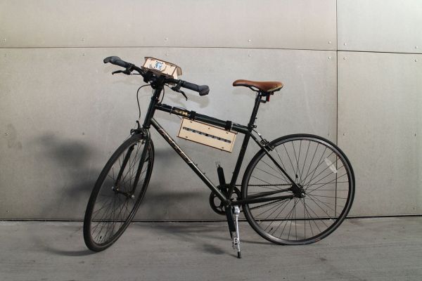
Step 1: Materials
Arduino Micro (RadioShack #: 276-258)
12V 10W halogen bulb (RadioShack #: 272-011)
(2x) 12V lamp (RadioShack #: 272-336)
(6x) LED holder (RadioShack #: 276-080)
(3x) green LED (RadioShack #: 55050659) web only
(2x) yellow LED (RadioShack #: 276-021)
red LED (RadioShack #: 55050657) web only
1 uF capactior (RadioShack #: 55047769) web only
(6x) 330 ohm resistor (RadioShack #: 271-1315)
(4x) 10K ohm resistor (RadioShack #: 271-1126)
(3x) N-channel MOSFET (RadioShack #: 276-2072)
74HC14 Schmitt Trigger (RadioShack #: 55050984) web only
reed switch (RadioShack #: 55050593) web only
on/off toggle switch (RadioShack #: 275-602)
(2x) SPST toggle switch (RadioShack #: 275-612)
(6x) terminal block (RadioShack #: 55055598) web only
(2x) 4 cell D battery holder (RadioShack #: 270-396)
(8x) D battery (RadioShack #: 23-2220)
(16x) 8-32 x 5/8″ screw
(16x) 8-32 nut
(4x) 4-40 x 1/2″ screw
(4x) 4-40 x 1.5″ screw
(8x) 4-40 nut
~40″ double sided Velcro
zip ties
.2 inch plywood
Bicycle
Step 2: Build the Circuit: Schematic
The circuit is composed of five main parts:
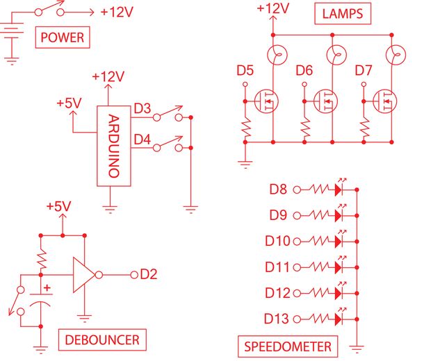
Power: Eight 1.5V batteries in series will give us ~12V. This system is attached to a large SPST toggle switch for control.
Debouncer: The reed switch is connected across the capacitor of an RC circuit. The analog output is fed into a 74HC14 Hex Inverting Schmitt Trigger which converts it into a digital signal, which is then fed into Arduino Micro interrupt 1 (digital pin 2). This chip is powered by the 5V from the Arduino.
Speedometer: Six LEDs are attached via current limiting resistors directly to the digital output pins of the Arduino.
Lamp Control: Three lamps are connected to N-channel MOSFETs. Each MOSFET has a 10k pulldown resistor on its gate pin, which is control by a digital output pin.
More detail: Bike Dashboard
- How is the power supply configured?
Eight 1.5V batteries are connected in series to provide approximately 12V. - What component converts the analog signal to digital?
A 74HC14 Hex Inverting Schmitt Trigger converts the analog output from the RC circuit into a digital signal. - How does the system detect speed?
A reed switch connected across a capacitor in an RC circuit feeds data into the microcontroller. - Which pins on the Arduino are used for the speed sensor?
The digital signal is fed into Arduino Micro interrupt 1, which corresponds to digital pin 2. - How are the six LEDs controlled?
Six LEDs attached via current limiting resistors connect directly to the digital output pins of the Arduino. - What controls the three lamps in the system?
Three N-channel MOSFETs control the lamps, with each gate pin managed by a digital output pin. - Why are pulldown resistors used on the MOSFET gates?
Each MOSFET has a 10k pulldown resistor on its gate pin to ensure proper operation. - Can I use this system without a bicycle?
The project description lists a bicycle as a required component for the final build.
