Summary of Autonomous Paintball Sentry Gun using Arduino
This project builds an autonomous sentry gun that tracks, aims, and fires using a webcam, computer vision software, an Arduino microcontroller, and servo-controlled airsoft or paintball gun mounting. The tutorial covers parts, Arduino setup, servo wiring, mechanical construction, software installation (Processing + libraries), calibration, and operation modes (manual/autonomous), with emphasis on balance, stability, and separate servo power.
Parts used in the Autonomous Paintball Sentry Gun:
- Airsoft or paintball gun (projectile dispenser)
- Webcam
- Computer or laptop to run Processing
- Arduino microcontroller (e.g., Arduino Uno)
- 3 servo motors (pan, tilt, trigger)
- Assorted screws, nuts, and bolts
- Wood or metal for construction (base/tripod)
- USB A to B cable
- 22 gauge solid wire
- Servo battery pack (separate servo power source, e.g., 4 C or D cells)
- Optional: servo power switch, safety switch, reload switch
- Optional: LED indicators (USB status, firing)
Make your own, custom AUTONOMOUS SENTRY GUN!
A Microcontroller Contest Finalist and Runner Up Winner.
This instructable is out-of-date. For the most recent version of the tutorial, see the website . Cheers!
This sentry gun autonomously tracks, aims, and shoots at targets, using:
-An airsoft or paintball gun
-A webcam to find targets
-A computer to process the video feed and aim the gun
-Servo motors to physically aim the gun and squeeze the trigger
-A sturdy tripod base
-A microcontroller to interface between the computer and the servo motors
-Lots of camo paint
The end result is a paintball/airsoft spewing robot, that can turn the tides of any match.
Video if it in action here .
Want to build your own?
You’re in luck! All the help and information you will need is here, and the software is free and open-source. Lots of people have already used this system in their own sentry guns, with successful results.
So go ahead, make your own, and soon your own backyard will be no-man’s land, too!
P.S. take pictures during the project, and when you are finished, send me a picture, and a description of your project, and I will feature it on the Successful Projects page of my website. Thanks!
Step 1: Parts List
Airsoft / paintball gun, or other ‘projectile dispenser’
$30 Webcam
$25 Arduino (or equivalent)
$27 3 Servo motors (pan, tilt, trigger) $9 ea.
$10 Assorted screws, nuts and bolts
$9 Wood/metal for construction
$5 USB A to B cable
$2 Some 22 gauge solid wire
$2 Servo battery box
$110 TOTAL
Also, you will need a laptop or computer to run the sentry gun program. $250 for a cheap netbook, if you don’t have anything else…
Step 2: Arduino
What’s an Arduino? …and how do you pronounce that, anyway?
An Arduino is a microcontroller. It plugs into a computer with a USB cord. On the Arduino board, shown below, there is an ATMega328 microchip, as well as 14 digital input/outputs, 6 analog inputs, and a USB port.
That’s not all, but it’s everything that you will need to know about, to build a sentry gun. For complete details on the Arduino board, go to http://arduino.cc/en/Main/ArduinoBoardUno.
You will use the Arduino board to take commands from the computer, and drive the servo motors as the commands dictate. Also, it will provide you with hookups for expanding your own ciruit easily afterwards.
Where to buy your own Arduino board
Step 3: Servo Motors
To control the movement of the gun, you will use 2 servo motors.
The “pan” servo controls the side-to-side movement of the gun.
The “tilt” servo controls the up-down movement of the gun.
Your remaining servo motor will be used to squeeze the trigger of your gun.
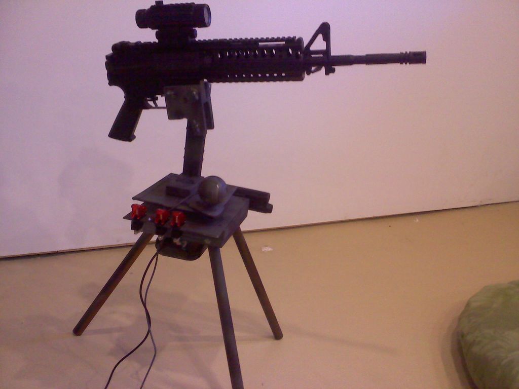
For heavy guns, such as the paintball gun shown below, you might want to get some stronger servo’s
Step 4: Constructing the Base
Now is time to put everything together. How you do this is largely up to you.
Some design considerations:
The gun should be balanced on the tilt servo. Find the gun’s center of gravity, and mount it at that point. This is so the servo dosn’t have to waste energy trying to keep the gun level. IMPORTANT: when the servo has no power supplied to it, the gun should tilt freely, and when you move it with your hand it should not return to level – rather it should stay right where you let go. Spend a lot of time getting this balance just right, it is a major factor in the effectiveness of your finished sentry.
Stability is key. You want a strong, solid sentry. Vibration will cause a lot of issues with the camera later, if you don’t suppress it now. I’m not going to teach you how to build well, but keep in mind that screws and bolts are better than nails, nails are better than zip ties, zip ties are better than staples, and even staples are better than duct tape.
The webcam must be solidly mounted to the base. You want it close to the gun, but the gun barrel can’t ever move into the camera’s view – it will see that as a target. Also, the webcam should be as solid as possible – vibration from the servo’s and gun firing will mess it up.
Depending on the expected use for the sentry (airsoft? paintball? water jet? laser?), you may need to add a durable compartment to hold the electronics.
Finally: tripods are cool, but they can be prone to a lot of shaking if built badly, or if you use a flimsy camera tripod. Surveyor’s tripods are great for sentry guns – they are heavy, stable, and often adjustable too.Step 5:
Step 5: Wiring
Arduino :
The Arduino connects to the computer through the USB A to B cord. This also powers the Arduino. Various other things wire to the Arduino:
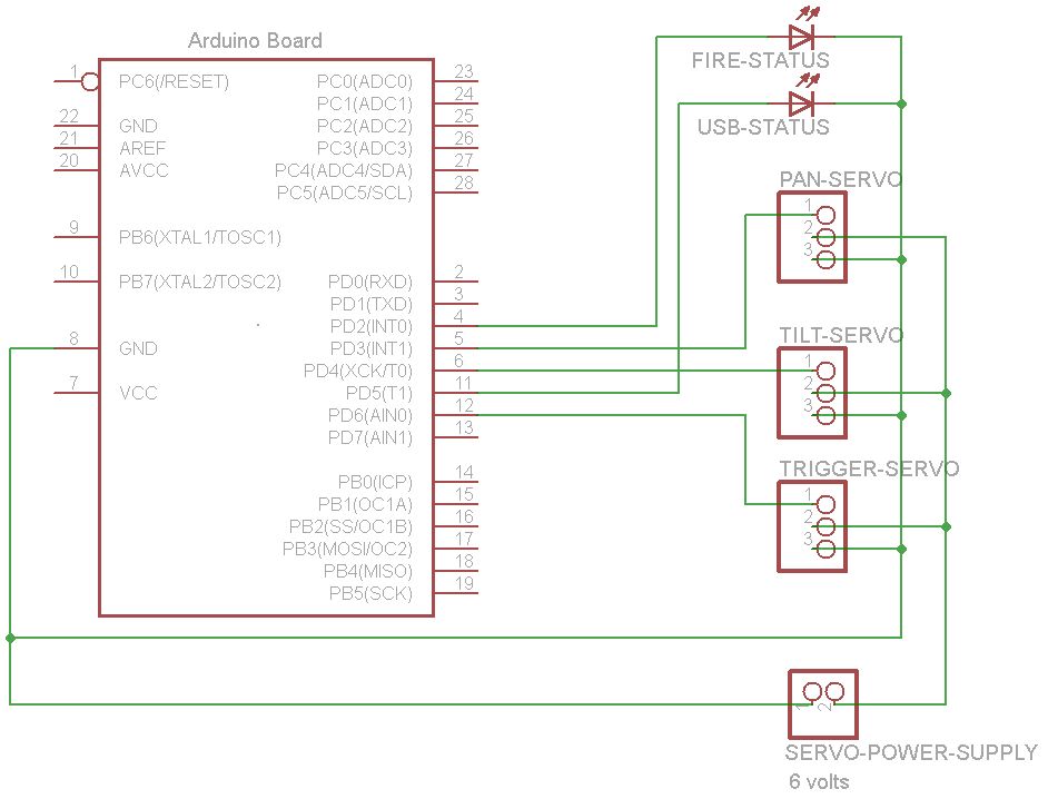
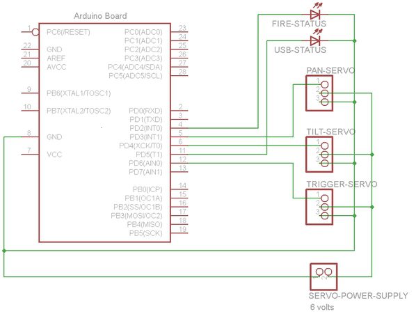
Here’s a wiring schematic , and you can get a sentry shield if you want an easy solution.
Servos :
You will need a seperate power source for your servo’s. I reccomend 4 C-cell or D-cell batteries, wired in series to make 6V. Check the data sheet to find the power consumption for your servo’s!
Servo motors have three wires: power, ground, and signal. Each servo’s power wire is typically red, and should be connected to the (+) wire from your servo power source. The ground wire is typically black or brown and should be connected to a ground pin on the Arduino board, and to the (-) wire of your power source. The signal wire is typically yellow, orange or white and should be connected as follows: The x-axis servo’s signal wire goes to the Arduino’s digital I/O pin 3, the y-axis servo to pin 4, and the trigger servo to pin 6.
You can also add some optional switches and LED’s , but they are not necessary:
-USB status indicator LED to digital I/O pin 5
-firing indicator LED to digital I/O pin 2
-a “power switch” between the (+) from the servo power source and the servo’s, to turn off the servo’s and save battery power
-a “safety switch” between the (+) from the servo power source, and the trigger servo, (but after the ‘power switch’), to turn off the firing functionality easily and quickly (in an emergency)
-a ‘reload’ switch, wired between +5V from the Arduino and digital I/O pin 7, to set the gun in a programmable position convenient for reloading
Solder everything if you can. If you want, make your own arduino ‘shield’ with all the conections. This allows you to “plug in” the Arduino, and “unplug” it when it is needed elsewhere, without losing track of which wires go to which pins.
Step 6: Software
Now you have your sentry gun built, the wiring finished, and no doubt you want it to do something!
Before you plug your Arduino into your computer, go download the Arduino IDE .
If you have a Diecimila or older board, set the Power Jumber to USB.
Now, plug your Arduino in – the green Power LED on the Arduino should light up, and the orange LED might flash a few times. Good job!
The Arduino IDE is what you will use to load the Arduino program onto your board. However, you will need the seperate, Processing IDE to run the computer side of the code. This does the camera tracking, and sends commands to the Arduino.
Go download the Processing IDE .
Open both Processing IDE and Arduino IDE. They should look very similar.
With a little bit of trial-and-error on the code, you should have a working sentry in no time! So get started typing!
Just kidding, of course.
The next thing you need to do is download the JMyron, blobDetection, and controlP5 libraries from processing.org. Find the link to each library on that page. The instructions for downloading each one can be found by clicking on it’s link.
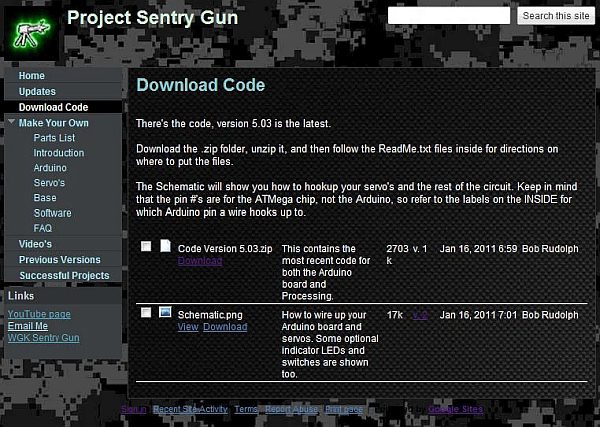
You are ready to go get the code! Download the latest version it from my website . After you have saved it to your computer, unzip the folder, and follow the directions in the strategically placed README.txt files.
Open the Arduino code in the Arduino IDE. Make sure you have selected the proper board and serial port from the Tools menu. Next, click ‘Verify’, wait for it to say “done compiling”, then click ‘Upload’. The RX and TX LED’s on the Arduino board should pulse a little, then stop.
Congrats! You have finished programming the Arduino!
Plug in your webcam. Install the drivers, if you haven’t already.
Now, open the Processing code in the Processing IDE. Click ‘Run’, and watch the magic happen!
Of course, for many of you this will not work on the first try. Don’t get upset, it’s normal. Pop me an email with any problems, or leave a comment below.
A tip for Windows 7 users, from ljfa321:
If you are getting this error when you try to run: processing.app.debug.RunnerException: UnsatisfiedLinkError: D:\Software\processing-1.2.1\libraries\JMyron\library\JMyron.dll: Can’t find dependent libraries:
“Reason : Windows 7 doesn’t come with MicroSoft C libraries, which were normally include in the other (older) Windoes system.
This means there are two files missing in the Windows 7 system: MSVCP71.DLL and Msvcr71.dll
Solution : Download these two files from here:
http://www.addictivetips.com/?attachment_id=38105
AND!
For Windows 7 32-bit OS: put both dll files inside Windows/System32 folder
For Windows 7 64-bit OS: put both dll files inside Windows/SysWOW64 folder.”
Step 7: Using the Software
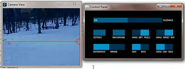
When you run the code, two windows should pop up. One is the Webcam View and the other is the Control Panel.
In Manual Mode, you can aim and fire by pointing and clicking on the webcam view. In Autonomous Mode, the software takes over, and your gun gains a life of it’s own! Give it a little time to adjust to the background, and then it will shoot at anything that enters its view.
Play around with the other functions as well – Auto/Semi-auto, hide camera view, etc.
Calibrating – your servo and camera arrangement is probably unique, so you will need to calibrate it the first time.
You can do this by adjusting the values of xMin, xMax, yMin, and yMax, at the beginning of the code. Play around with them untill you have the gun aiming where you point the mouse on the webcam view. A useful tool to do this is to watch the numbers scrolling by at the bottom of the Processing IDE while you run the code.
You may also need to calibrate the servo positions set in the Arduino code:
To set the reloading position, change these lines:
if(digitalRead(7) == HIGH) {
xPosition = 110;
yPosition = 135;
fire = 0;
}
To set the home position (no USB communication), change these lines:
if(idle) {
idleCounter++;
if(idleCounter > 10000) {
analogWrite(5, 50);
delay(250);
digitalWrite(5, LOW);
idleCounter = 0;
}
else{
digitalWrite(5, LOW);
}
xPosition = 110;
yPosition = 100;
fire = 0;
}
To set the ‘squeezed’ and ‘not squeezed’ positions for the trigger servo, change these lines:
void Fire(int selector) {
if(selector == 1) {
fireTimer++;
if(fireTimer >=0 && fireTimer <= triggerTravelMillis) {
trigger.write(90);
digitalWrite(2, HIGH);
}
if(fireTimer > triggerTravelMillis && fireTimer < 1.5*triggerTravelMillis) {
trigger.write(140);
digitalWrite(2, LOW);
}
if(fireTimer >= 1.5*triggerTravelMillis) {
fireTimer = 0;
}
}
if(selector == 3) {
trigger.write(90);
digitalWrite(2, HIGH);
}
}
void ceaseFire(int selector) {
if(selector == 1) {
fireTimer = 0;
trigger.write(140);
digitalWrite(2, LOW);
}
if(selector == 3) {
trigger.write(140);
digitalWrite(2, LOW);
}
}
- What components are required to build the sentry gun?
The article lists an airsoft/paintball gun, webcam, computer, Arduino, three servos (pan, tilt, trigger), screws/nuts/bolts, wood/metal base, USB A to B cable, 22 gauge wire, and a servo battery pack, plus optional switches and LEDs. - How are the servos powered and connected?
Servos use a separate power source (recommended 6V from 4 C or D cells); power wires to the positive, grounds tied to Arduino ground, and signal wires to Arduino digital pins 3 (x axis), 4 (y axis), and 6 (trigger). - How does the Arduino interact with the computer?
The Arduino connects via USB to the computer; the computer runs Processing code for camera tracking and sends commands to the Arduino which drives the servos. - What software is needed to run the sentry gun?
You need the Arduino IDE to upload Arduino code and the Processing IDE to run the computer-side tracking code, plus Processing libraries JMyron, blobDetection, and controlP5. - How do I calibrate the camera and servos?
Adjust xMin, xMax, yMin, and yMax in the Processing code to match mouse aiming on the webcam view, and edit servo position values in the Arduino code for home, reload, and trigger positions. - Can the system be used in manual mode?
Yes; Manual Mode allows aiming and firing by pointing and clicking on the webcam view, while Autonomous Mode lets the software track and fire at targets automatically. - What construction tips improve performance?
Balance the gun on the tilt servo at its center of gravity, build a stable base to reduce vibration, mount the webcam solidly near the gun without the barrel entering its view, and use screws/bolts rather than tape for durability. - Are there recommended safety or convenience switches?
The article suggests an overall servo power switch, a safety switch to disable the trigger servo, optional LED indicators, and a reload switch wired to Arduino pin 7. - What issues might Windows 7 users face running the software?
Windows 7 may lack MSVCP71.DLL and Msvcr71.dll required by JMyron; the article advises downloading those DLLs and placing them in the System32 or SysWOW64 folder depending on OS bitness. - Where do I get the sentry gun code?
The article directs readers to download the latest code from the author's website and follow the provided README instructions after unzipping.