
I’ve been growing more and more interested in the idea of First Person Video (FPV) drone racing. I’ve recently acquired a small drone and wanted a way of timing my laps – this is the resulting project.
This drone landing pad features an integrated ultrasonic sensor that detects a drones presence. When a drone departs the Arduino starts a timer. When you return your lap time is displayed to you. You can either try to improve your personal best or challenge a friend to do better than you (if you trust them with your drone that is). It can be printed and assembled over a couple of days including the required printing time.
You can download the 3D cad parts from my Thingiverse page. https://www.thingiverse.com/thing:2832044
If you enjoy building this and using your own landing pad timer, please consider supporting the channel on Patreon: https://www.patreon.com/diymachines
Step 1: There Is a Video Available
If you prefer to follow a video, or want to watch me build mine before you build your own please see this video from my Youtube channel. When you’re ready, read on…
Step 2: Printing the Main Base
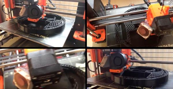
You’ll need to start by printing the main base. I printed mine in black to match the colour of the ultrasonic sensor, you can print yours in any combinations of colour you wish. Perhaps try a glow in the dark for low light races?
Step 3: Assembling and Attaching the Ultrasonic Sensor
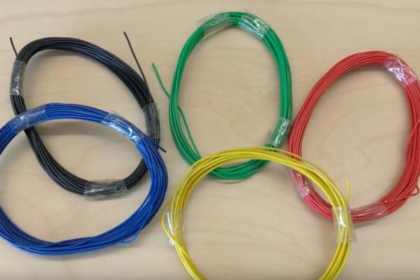
I’m using five colours of wire during this build, Black, Green, Red, Yellow and Blue. If you can use the same colours then you will find it much easier to follow along – but you can still build one with just a single colour of wire.
First cut one length of red at 7cm long and a 5cm length in yellow, blue and green.
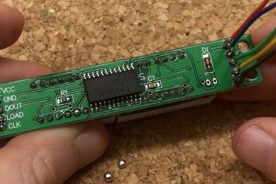
You will need to solder these on in the opposite direction then you would normally (take a look at the image above to see what I mean). They should be soldered as follows:
- Red –> VCC
- Green –> Trig
- Yellow –> Echo
- Blue –> Ground
Once this is done you can glue it in place using some hot melt glue.
Step 4: Attach Battery Holder
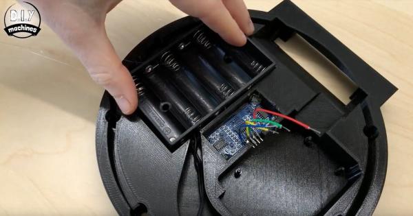
At the same time and whilst we have the glue gun heated up we can glue in place the battery holder.
Step 5: Assembling the Display
Now you need 5 wires, one of each colour cut to 19cm in length. You’ll need to expose a bit more of one end of each wire as one end will be soldered to the display whilst the other will be pushed directly into the headers of the Arduino to cut down on the amount of soldering required.
They will be soldered to the rear side of the display on the points as shown in the second image, use the third to follow which colour is soldered to which connection.
Step 6: Attaching Screen and Its Shield
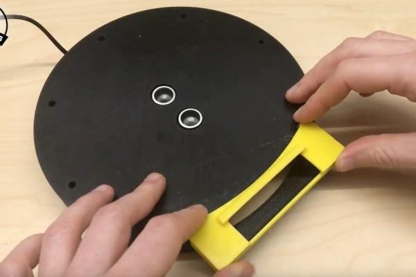
Next, print the shield for the screen. I chose to print mine in bright yellow to contrast with the black whilst also making it easier to see from your drones camera when you try to land on it.You attach this with some more hot melt glue.
You can also glue the seven segment display in place, this is also done with the trusty old hot melt glue gun. Use a little on each corner of the board and then insert from the underside of the base. Ensure that when you flip the base over and view it from the front, the decimal places are on the bottom of the display – if not then you’re about to insert upside down!
Step 7: Preparing Green LEDs
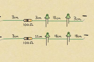
You now need the following wires which will connect along with the LED’s and resistors to create the two strings of Green LEDs:
- 18cm x3
- 3cm x x4
- 11cm x1
They then need soldering together with four green 5mm LEDs and two 100 Ohms resistors. Their colour markings go Brown-Black-Brown and then Gold at the end.
Make sure that the positive side of the LED (the longer leg) is connected to the positive side of the circuit. As current will only flow one way through an LED you’ll find it won’t work if one is attached the incorrect way.
Step 8: Attaching Green LEDs
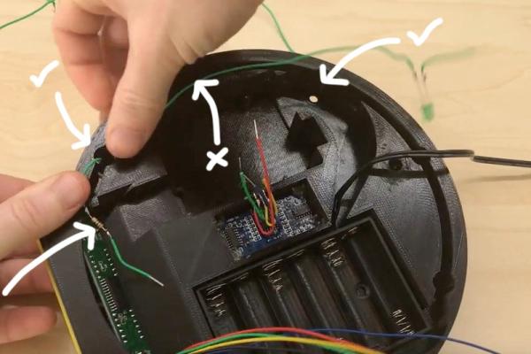
Once you have soldered them together we will add them to the main base. Make sure the end of the wire with the resistor is closest to the display and push the first LED through the first hole going clockwise around the display. Then skip the next hole, and push the second LED through the proceeding hole.
You can then use some hot melt glue to hold the LEDs in position from behind whilst also ensuring the two legs of each LED don’t come in contact with one another and shorten the circuit.
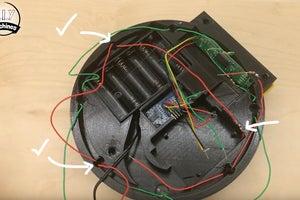
Repeat the same steps for the second string of LEDs but this time going anticlockwise from the display like in the third image.
And then again backfill the LEDs with some more of my favourite hot melt glue.
Step 9: Preparing and Attaching Red LEDs
Now we will work on the red LEDs, you’ll need to prepare another set of wires (see below), 3 red LEDs, 1 x 100Ohm resistor, and 1 x 220 Ohm resistor. Attach them again as shown in the schematic.
- 18cm x2
- 3cm x2
- 10cm x3
First we will add the string with a single LED in it. This wants to be added again with the resistor nearest the display plugging the gap when we work clockwise around the base. Don’t forget to add some glue.
The string with two wants to go around in the other direction.
Source: Automatic Drone Lap Timer – 3D Printed, Arduino Powered.