Summary of Automated Train Reverse Loop Using Arduino
This article details how to build an automated reverse loop for model train layouts using an Arduino microcontroller. This setup allows trains on single-track layouts to change direction without stopping, overcoming the limitations of turntables. The project involves isolating track sections, wiring a motor driver shield to control the locomotive and turnouts, and programming the Arduino to manage the sequence based on sensor input.
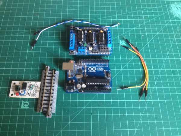
Parts used in the Automated Train Reverse Loop:
- Arduino microcontroller board (UNO, Leonardo, or MEGA)
- Adafruit motor driver shield
- 12-volt DC power source (battery or adapter with at least 1.5 amp capacity)
- Six male to male jumper wires
- 'Sensored' track
- Three female to female jumper wires
- Four insulated rail joiners
- N-gauge Kato Unitrack (or compatible track)
Making reverse loops can help in model train layouts to change the direction of trains, which cannot be done with turntables. In this way, you can create single-track layouts with a reverse loop on each end to run trains without any pause or interruption. So, without further ado, let’s get started!
Step 1: Gather All the Required Stuff!
For this project, here is the list of required parts and components:
- An Arduino microcontroller board, recommended ones are UNO, Leonardo, MEGA.
- An Adafruit motor driver shield.
- A 12-volt DC power source(can be a battery or an adapter with a current output capacity of at least 1.5 amp)
- Six male to male jumper wires:
- A pair to connect the turnout to the motor driver.
- Second pair to connect the power of the outer track to the motor driver.
- Third pair to connect the inner loop to the motor driver.
- A ‘sensored’ track.
- 3 female to female jumper wires(to connect the sensor to the Arduino board).
Step 2: Program the Arduino Board
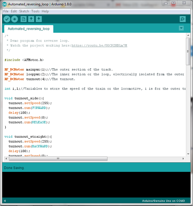
If you don’t have Arduino IDE on your computer, download it from here. The library for the Adafruit motor driver shield can be found here, in case you don’t have it in your IDE. Make sure you install this in your IDE before compiling the program. If you need help installing a library, check this link out.
Step 3: Isolate the Inner Loop Tracks
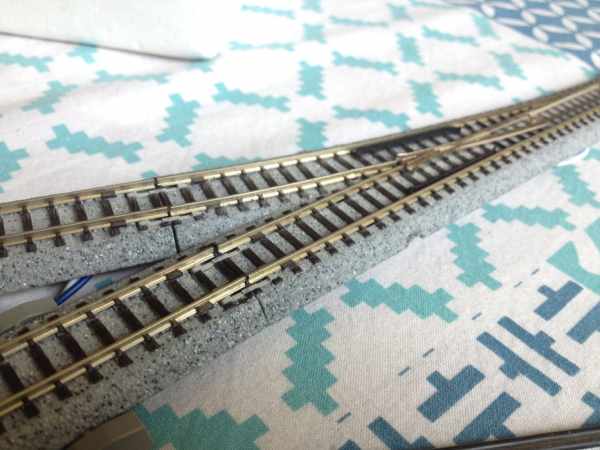
Using 4 insulated rail joiners, isolate the inner loop of track from the outer track. Click on the image for more info.
Step 4: Make the Layout
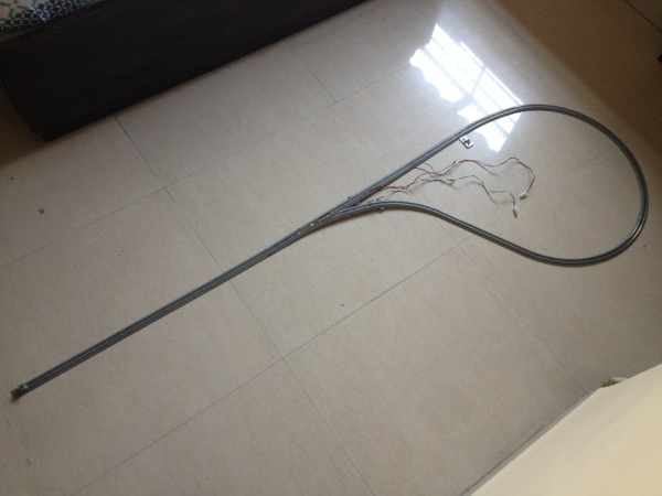
I used N-gauge Kato Unitrack to make this layout. You can use any other track as long as everything works properly.
Step 5: Plug the Shield on the Arduino Board and Make the Wiring Connections
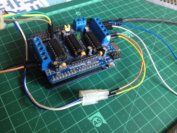
Before attaching the motor driver shield, make sure all of the pins are aligned and then push the shield down to attach it firmly to the Arduino board. When keeping the board in an upright position(see the above image) such that the analog input pins are on your side, make the following connections:
- Connect the turnout wires to the terminal block marked ‘M4’ by connecting the +ve or the red wire to the upper terminal and the -ve or the black wire to the lower terminal.
- Connect the power wires of the inner section of the loop to the terminal block marked ‘M2’. Connect it anyway for now and change the polarity later if the train or the locomotive moves in the wrong direction inside the loop or just stops.
- Connect the outer track’s power to the terminal block marked ‘M1’. Do the same later as you will do for the track power in the inner loop.
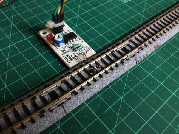
Connect the pins of the sensor as follows:
- VCC to +5-volts pin of the Arduino board.
- GND to GND pin of the Arduino board.
- OUT to A0 pin of the Arduino board.
Source: Automated Train Reverse Loop Using Arduino
- What is the primary benefit of using a reverse loop in model train layouts?
It allows trains to change direction on single-track layouts without any pause or interruption, which cannot be done with turntables. - Can I use different types of track for this project?
Yes, you can use any other track as long as everything works properly, though the author used N-gauge Kato Unitrack. - How do I isolate the inner loop tracks from the outer track?
You must use four insulated rail joiners to isolate the inner loop of track from the outer track. - Which pins on the Arduino should the sensor connect to?
The sensor VCC connects to the +5-volts pin, GND to the GND pin, and OUT to the A0 pin. - What is the minimum current output required for the power source?
The power source must have a current output capacity of at least 1.5 amps. - How many male to male jumper wires are needed for this project?
Six male to male jumper wires are required for connecting the turnout, power lines, and track sections. - Where should the turnout wires be connected on the motor driver shield?
The turnout wires connect to the terminal block marked 'M4', with the red wire to the upper terminal and black to the lower. - What happens if the train moves in the wrong direction inside the loop?
You can change the polarity of the connection later to correct the direction of movement.