For most of us during lock down, we have been practicing a lot of exercises. Either its some stretching or some muscle building exercises. But one issue that I have faced personally is keeping track of my workouts. I was unable to see my progress as there was not some sort of recording of my exercises. This let me to an uneven workout routine and was not motivated to increase my repetition.
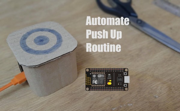
This is when I realized that I could build something that count the number of a particular exercise I practiced and store it in a database. The exercise I choose is Push Up. It is very effective and probably the one that I want to keep track of. So lets build an Automated Push Up counter.
Supplies
Material :
- Cardboard
- Esp8266 Board
- Small Breadboard
- Jumper male to female x2
- Resistor 1k ohm x 1
- Limit Switch x1
- Glue stick
Tools:
- Scissors
- Ruler
- Pencil
- Glue Gun
Software:
- Arduino IDE
- IFTTT website
- Google Sheet
Step 1: Concept
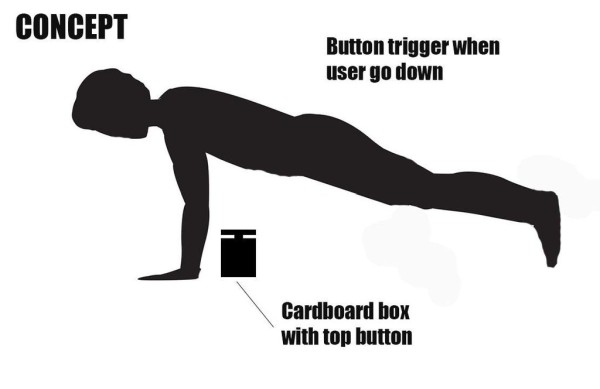
Firstly we need to have an idea on how to make it. I have made some research and saw that some people uses an ultrasonic sensor to detect your position. But I decided to use a limit switch as it is simple and easy to use. I want it to be a small box that you place on the ground at your chest position with a top button. Whenever you reach the bottom of your Push Up, the button trigger and increases a counter.
For the Box I wanted to 3d print it but did not have access to a 3d printer. So I planned to make it totally with cardboard which is available everywhere.
I will code the system so that it detect the button trigger, increase a counter and update a database. For this I will use an esp8266 WiFi module. This will make the connection of the trigger and the Database. For the Database I want to go simple using Google Sheet.
To communicate with the Database, I will use IFTTT, as simple user friendly site that help you to Automate things easily.
Step 2: Marking for the Cardboard Box
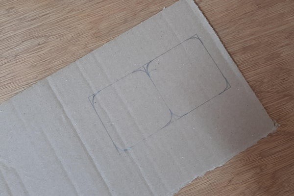
To make the box structure I will use 2 rounded square cardboard with another cardboard rectangle for the surrounding. You can use a pencil and a ruler to mark the lines. The line should be perpendicular to each other in order to have a squared box.
The squares are 60mm x 60mm with a rounder corner of diameter 10mm and the long rectangle is 230mm long and 60mm high.
Step 3: Cutting the Cardboard Parts
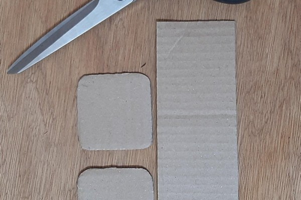
The 2mm cardboard can be easily cut using a pair of scissors. On one square panel I have also make a small hole so that I can wire the limit switch. This hole is just 1mm inside the cardboard so that it hold the limit switch in place. You can use a scissors or even a cutter to remove that part.
For the surrounding part you will need to bending it as the picture above to make it easier to glue latter
Step 4: Install Limit Switch
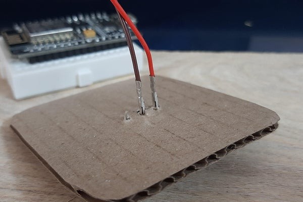
Now as you can see in the picture above I have not completely cut the switch hole. This will keep the limit switch in place when force is apply on it. You can glue the switch in place to make it stronger.
For the connection you can use two male to female jumper. This will be tight and hold in place perfectly. The advantage I get when using this type of limit switch is that it can work as a spring too. Which mean that I do not need to put a spring to return the button at its initial position after push.
Step 5: Wiring As Per the Schematic
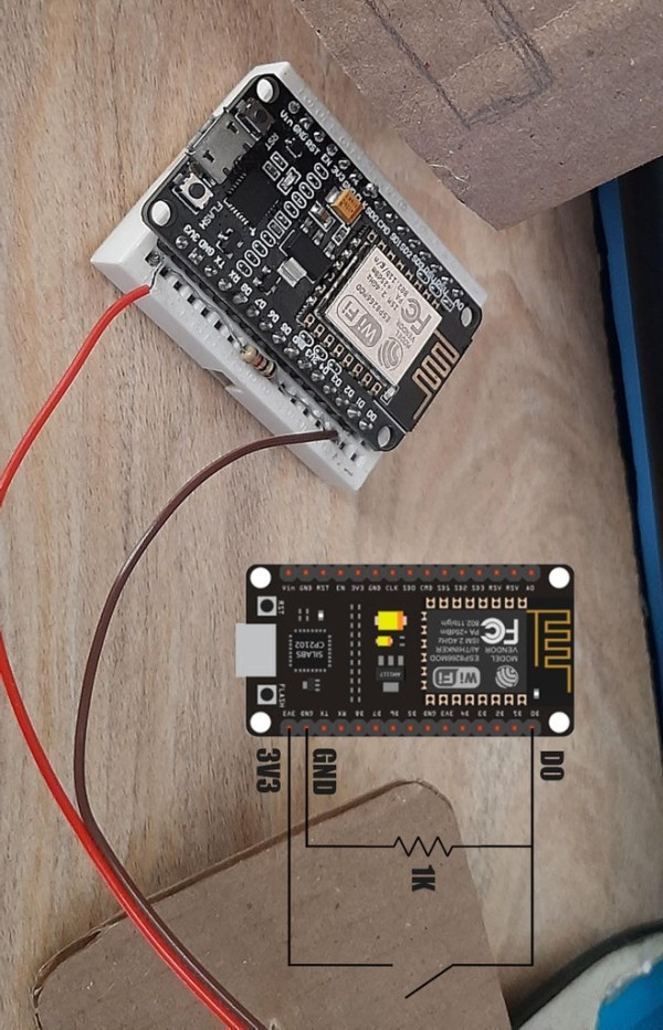
For the wiring, you will first need to push the Esp8266 in the breadboard until the board lay flat on the breadboard. You can now connect the resistor and the two jumper cable from the limit switch. The connection is simple and the schematic is available on the photo above.
Why a resistor?
The resistor is put in the schematic to prevent overload of the GPIO pin when you press the switch. For example, when you press the button, a maximum of 3.3V will flow into the GPIO pin, you will able to detect it in the code and the rest will be flow to the GND pin.
Step 6: Assembly
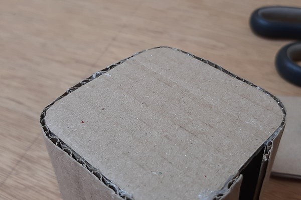
I am using Glue gun to assemble all the parts together, You need to glue the bottom first as this will be easier. Then you remove the plastic cover from the breadboard and stick it to the bottom. Now you glue the Second part with the limit switch. I have kept a 10mm space from the top so that I can put a cardboard switch cap.
I have also make a small hole on the side for the USB cable to connect to the board.
Step 7: Make Top Cover
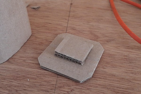
For the cap you will need another 60mm by 60mm square panel and glue two small pieces in the middle to act as an elevator. Then you glue another 30mm by 30mm square panel to the top of the two stacked parts. This will be the part that press the limit switch. And as you can see it fit perfectly in the 10mm gap I kept.
Now you can add a decoration or a sign on the top to indicate that this is a button.
Source: Automate Push Up Routine With ESP8266